The Zishan dsd's corner

Nov 2, 2020 at 11:36 PM Post #3,031 of 3,717
@moshe tes
There are too many post with important information and mods to post, you need to search and read parts of the thread.


I think I used this inductors, maybe others can recommend more:
https://www.arrow.com/en/products/srp4020ta-4r7m/bourns

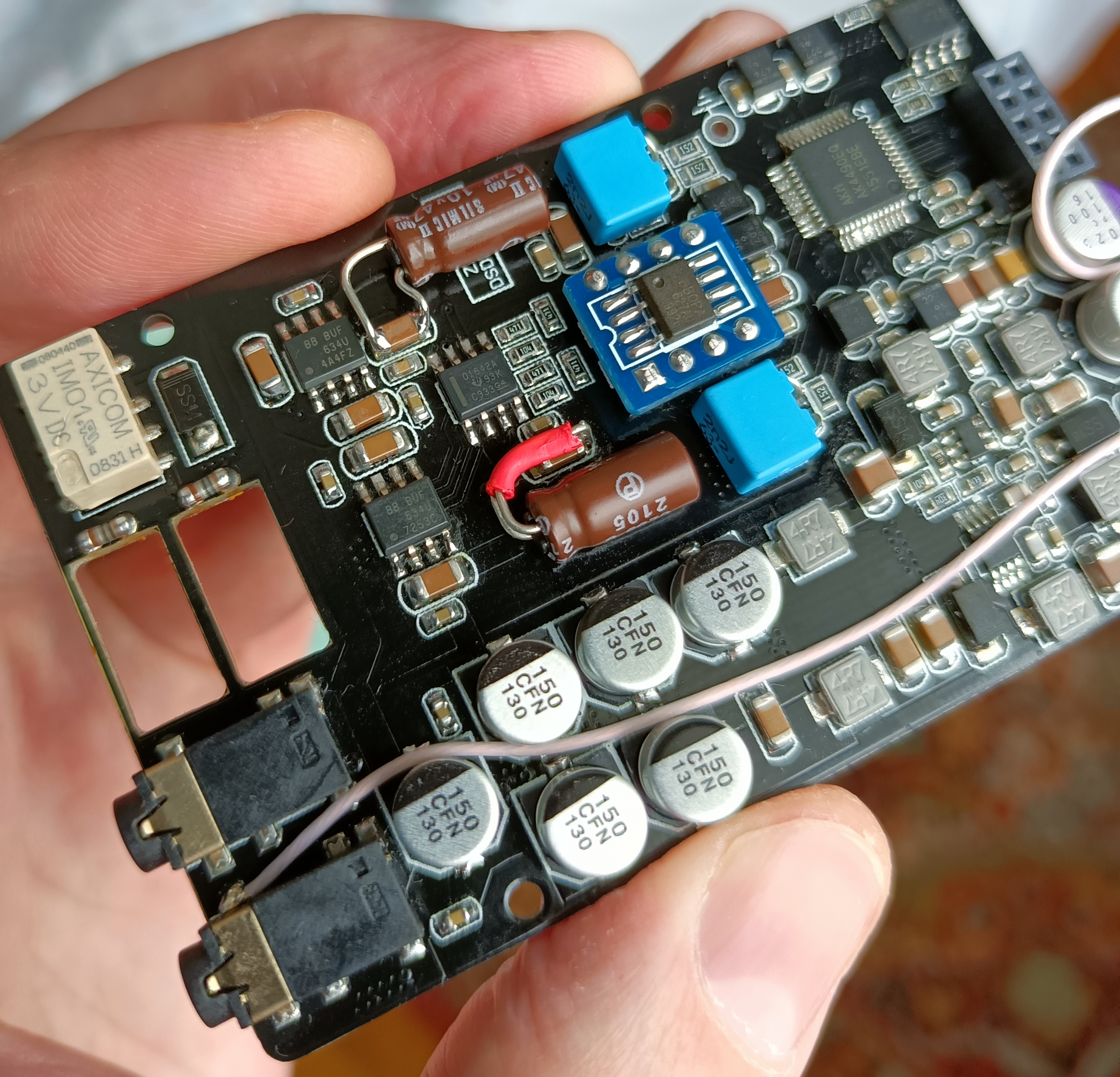
Some mods I did in my player:
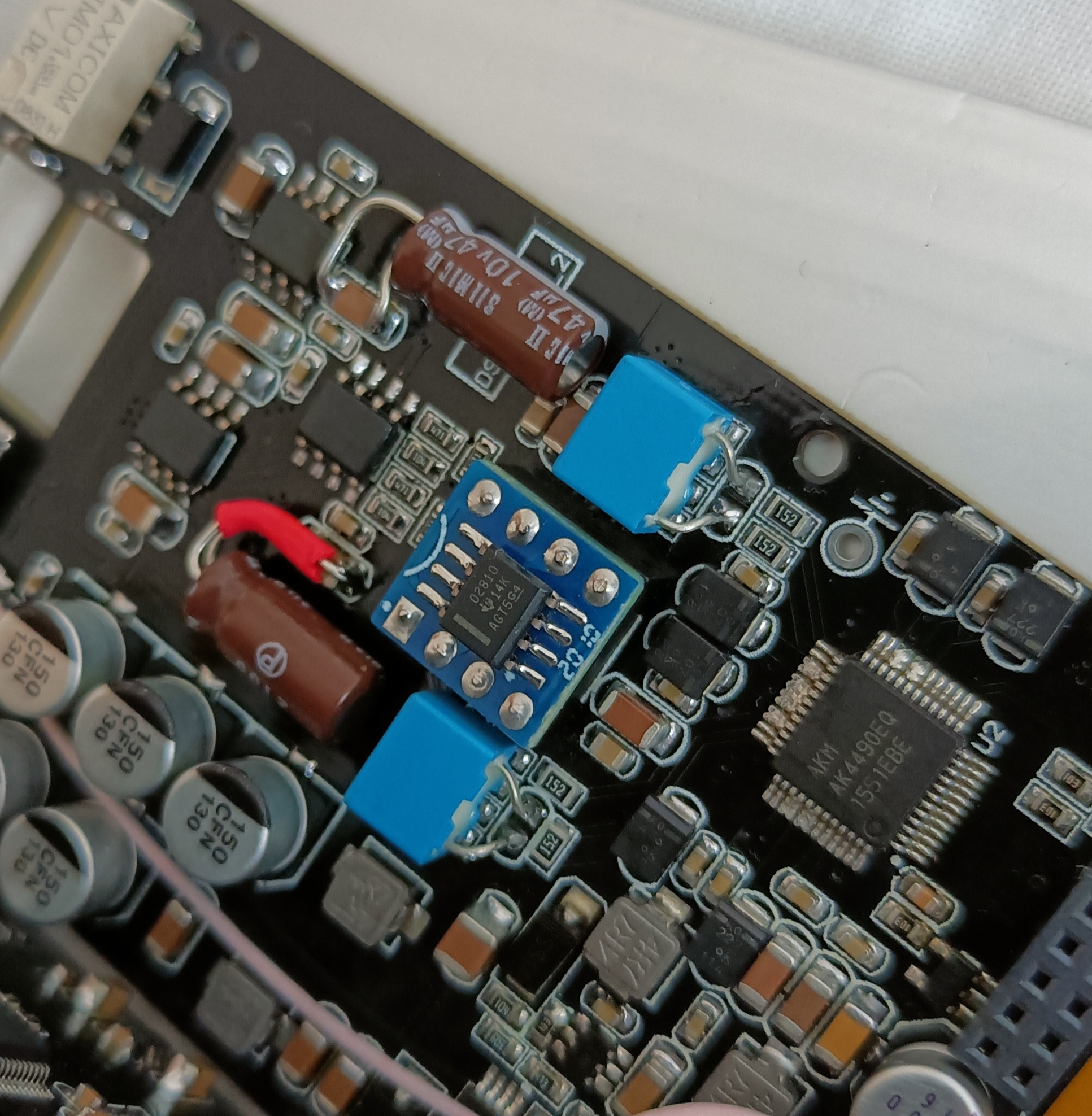
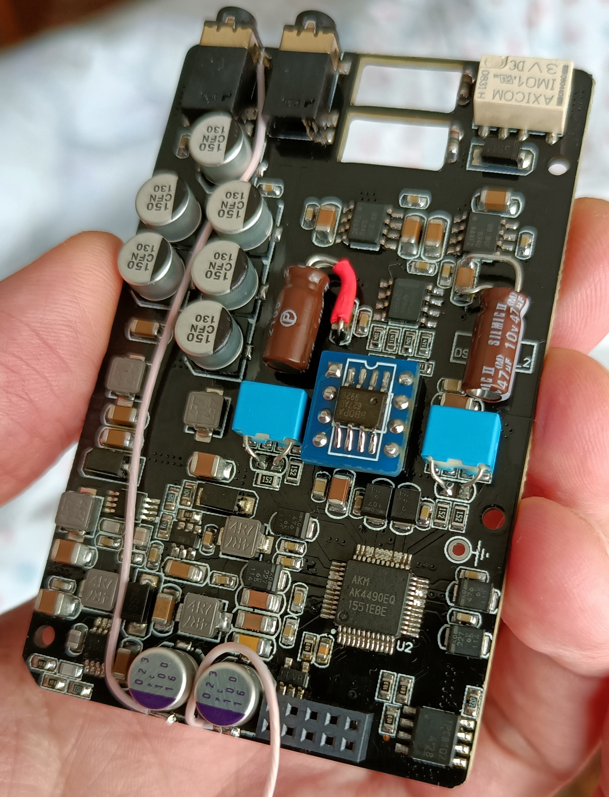
- Replace the opamps and the electrolytic caps for genuine ones.
- Replace the LDOs and oscilattors.
- Replace all the ceramic caps for X7R from known brands, small values you can try COG/NPO.
(I tried COG/NPO and even other cap types in the opamps circuit, some I like the sound others I hated the sound, in the end I think I used X7R there)
- Replace and increase the tantalum caps in the dac
- Replace the resistors with susumu brand (I use 0.5% 25ppm 0.1Watt 0805, but there are even better models from this brand)
- Follow the DAC datasheet and add the missing caps
- Increase the power reserve caps, add bypass caps near the opamps local power reserve
- Remove or replace the transistor circuit at the output
- Increase the opamp voltage
- etc.

As much as I would like, I don't have free time to reply with more detail.


Thank you! This is very helpful. I am familiar with all except ---- "Increase the power reserve caps", "Remove or replace the transistor circuit at the output", "Increase the opamp voltage".

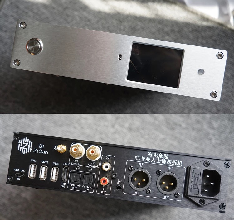
I am mostly interested in dealing with the discrete buffer (transistor circuit) because I have a feeling it is messing with the sound quality. And of course increasing the opamp voltage. I assume I will have to modify the power source for that. First I need to understand the board layout. I am not sure what exactly is going on with the side that has the white relay at the top and inductors at the bottom. The rest of the board, I have an overall understanding. Thanks for the links. I understand if you do not have time. I would really appreciate a basic overview of why you would get rid of the discrete buffer and how to increase the op amp voltage. Just a few sentences not necessarily specifics, I think I can figure out the specifics.
 
Nov 3, 2020 at 5:19 AM Post #3,032 of 3,717
- To increase the power reserve caps and get more space in my case I used 4x220F (with legs and laying down on their belly) instead of the 6x68uF SMD that were there.
I use this ones https://www.arrow.com/en/products/16zlh220mefc6.3x11/rubycon
You can use any you want provided they fit and are low ESR.
I filtered all arrow caps,with this criteria:
size:6.3 X 11mm, >=16V, higher capacitance and lowest ESR.

These capacitors are only power reserve connected to the opamps power supply pins.
You don't need to modify the power supply to the opamps to replace them, it was the other way, I wanted to increase the power supply voltage to the opamps to 12V and wanted to make sure the power reserve caps were rated 16V or more, also the 10uF ceramic local power reserve caps near the opamps need to be 16V or more (I bought 10uF 25V or 50V can't remember...I got the best price/deal)

- If you wish to increase the power supply to the opamps, google MP1542 datasheet, zishan uses an DC-DC converter labeled 1542D to increase the battery voltage to +-9V to feed the opamps.
Vout = 1.25 × (1 + R1/R2)
Factory default MP1542 resistors:
304 code = 300K
473 code = 47K
R1=300K, R2= 47K => Vout = 1.25 × (1 + 300/47) = 9V
(Careful here, do not fry the opamps or caps with too much voltage)

- The relay:
https://www.head-fi.org/threads/the-zishan-dsds-corner.826185/page-160#post-15025178
https://www.head-fi.org/threads/the-zishan-dsds-corner.826185/page-202#post-15945102
---
I removed the discrete transistor buffer (what I called transistor circuit at the output), because I hated it's sound, completely destroyed my opamps sound. I wanted to replaced it with another circuit, but didn't had the time to do it, so I have it without output buffer.
---
The power supply goes like this, batt has 3.7V or lower when with lower charge.
They use 3.3V LDOs (connected to the batt power line) to supply 3.3V to several parts in the boards (including the DAC).
They use a DC-DC converter (B6288b) to increase the batt voltage above 5V followed by a 5V LDO to supply 5V power line to the DAC.
They use a DC-DC converter (MP1542) to increase the batt voltage to 9V (without any LDO) followed by 2 inductors to filter some noise and power the opamps +-9V.
The -9V is made with a with 2 diodes and caps explained in the MP1542 datasheed example circuit. (I replaced all the K14 schottky diodes)
The inductors are near these DC-DC convertes to make it work, and the last two (near the opamp reserve caps) to filter noise.
At some point I even replaced the MP1542 and their circuit values with adp1613, sounds as good.
---
This is from top of my head, so pls if anyone finds any mistake just correct.
I made all those mods because I want to experiment, some give huge gains in sound, others are very subtle, all is not necessary.
I would start by replacing all the opamps and the electrolytic caps.
Then the LDOs and maybe the oscillators.
Then go from there if you need more.
 
Last edited:
Nov 3, 2020 at 10:06 AM Post #3,033 of 3,717
- If you wish to increase the power supply to the opamps, google MP1542 datasheet, zishan uses an DC-DC converter labeled 1542D to increase the battery voltage to +-9V to feed the opamps.
Vout = 1.25 × (1 + R1/R2)
Factory default MP1542 resistors:
304 code = 300K
473 code = 47K
R1=300K, R2= 47K => Vout = 1.25 × (1 + 300/47) = 9V
(Careful here, do not fry the opamps or caps with too much voltage)


What do you think of increasing the voltage to match AK4497 LPF spec sheet which would be 15V using this formula you outlined?
 
Nov 3, 2020 at 1:27 PM Post #3,035 of 3,717
What do you think of increasing the voltage to match AK4497 LPF spec sheet which would be 15V using this formula you outlined?

I don't really know, you'll have to see if the opamps you use allow it and if there is any advantage using that voltage with those opamps. Maybe others can add more about this topic.

You'll have to use caps rated above 16V, read the caps datasheets, many only work bellow their rated voltage. The power reserve caps probably will be bigger.

Thank You Merlin for sharing!

Main Question:
DSDs Dual 4479 working on 2,5mm jack as full balanced player?
2x DAC and 2x OPAmps in separate 4 channels?

I don't have that player, but each dac will work in mono configuration, search the dac datasheet for the word mono and you'll find better specs in that configuration. Also channel separation will be better, that makes better stereo image.
 
Last edited:
Nov 3, 2020 at 2:21 PM Post #3,036 of 3,717
I think I am going to try to increase the voltage to 15V, but I hesitate somehow thinking it will be a problem with the volume adjustment. I am not sure how that works. It might be designed for a 9V system. Tell me if I'm mistaken.
 
Nov 3, 2020 at 3:11 PM Post #3,037 of 3,717
No, the opamp gain will change the volume, not it's power supply.
(See the gain in the 1rst link I quoted, with the circuit and gain resistors)
You'll need to replace all the capacitors that will be at +-15v with appropriate rated voltage.
Also make sure all opamps support that voltage.
I'm not aware of any real advantage to go +-15V in our use.
Let's await for others feedback on this.
 
Nov 3, 2020 at 3:42 PM Post #3,038 of 3,717
Thank You Merlin for sharing!

Main Question:
DSDs Dual 4479 working on 2,5mm jack as full balanced player?
2x DAC and 2x OPAmps in separate 4 channels?


No! This is a linear output for a balanced amplifier!

I already wrote about this. My work for DSD 4497 DUAL

http://player.ru/showthread.php?t=180748&page=426&p=3044007&viewfull=1#post3044007

Photos of my work for DSD 4497 DUAL:


I don't support the idea of raising the voltage!
This will cause a lot of problems and deterioration
of the device characteristics...
 

Attachments

  • Zishan DSD AK4497 DUAL SL MOD 1.jpg
    Zishan DSD AK4497 DUAL SL MOD 1.jpg
    3.1 MB · Views: 0
Last edited:
Nov 3, 2020 at 4:30 PM Post #3,039 of 3,717
No! This is a linear output for a balanced amplifier!

I already wrote about this. My work for DSD 4497 DUAL

http://player.ru/showthread.php?t=180748&page=426&p=3044007&viewfull=1#post3044007
I was read several times about your work but I see google translate from Russian to Polish is quite inaccurate :( I thought 2,5mm balanced without any amplification is on DSDs 4499 not Dual 4497.

I am waiting for balanced IEMs 32Ohms 109dB so I need also 2,5 balanced amplifier to run it property? I don't see any this kind portable amp.
 
Nov 3, 2020 at 5:05 PM Post #3,042 of 3,717
I don't support the idea of raising the voltage!
This will cause a lot of problems and deterioration
of the device characteristics...

I am trying to replicate the AK4497EQ datasheet as it is based on +-15V. I am also using OPA1612 for the low pass filter circuit just like the datasheet. I intend to have an OPA1622 as the main driver. I will still need to figure out the circuit for the OPA1622 of course. If you have some tips, I would appreciate it. Of course I will need to replace all caps. What issues do you think will arise from increasing the voltage? Would it cause instability with the main battery supply circuit due to more current being drawn? I still need to figure out the buffer circuit as well. I have been researching buffers all day and trying to learn about impedance. I am new to this sort of pure electronics stuff. My hobby was mostly with digital electronics and microcontrollers.
 
Nov 3, 2020 at 5:34 PM Post #3,044 of 3,717
I will still need to figure out the circuit for the OPA1622 of course.
I am not a fan of amplifiers on a single op-amp,
I prefer complex composite circuits. But I would prefer AD8397.


I would not raise the voltage, as this will degrade the performance of the power supply system and as a result will add a lot of noise peaks, degrade the characteristics of IMD, TND under load.
I tried to do that.
 
Last edited:

Users who are viewing this thread

Back
Top