The DSD uses a 2.5mm TRRS jack for Balanced output, and this drawing shows only one 2.5mm pin-out. That wiring is correct:
Sleeve = L-
Ring-2 = L+
Ring-1 = R+
Tip = R-
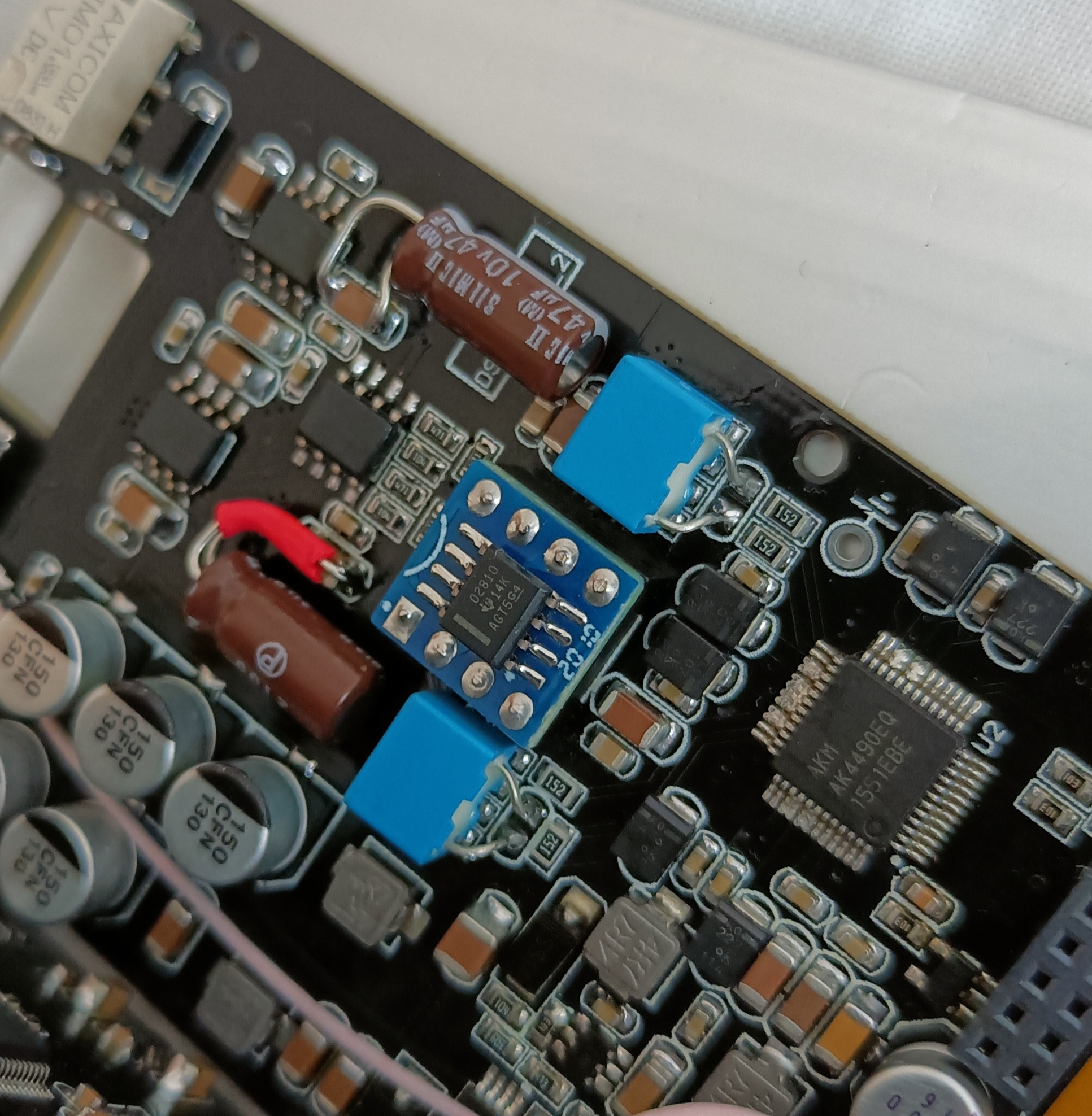
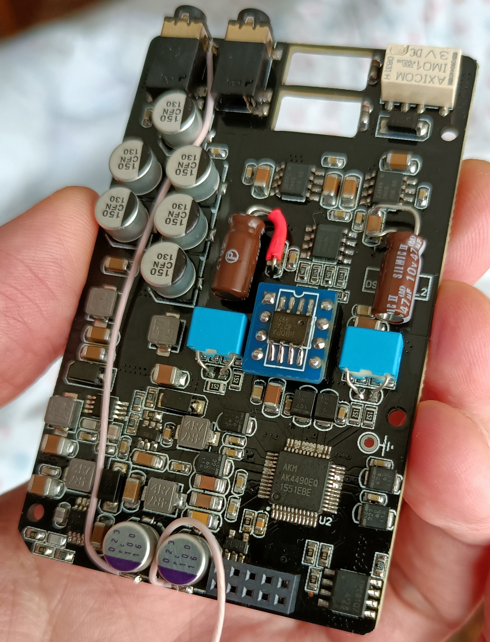
Just installed 2 ada4637 (browndog style custom support: had to make it by myself since there is no room): compared to the original opamp it is simply FANTASTIC: instrument separation, clarity and soundstage jump to another level.
Very, very much recommended.
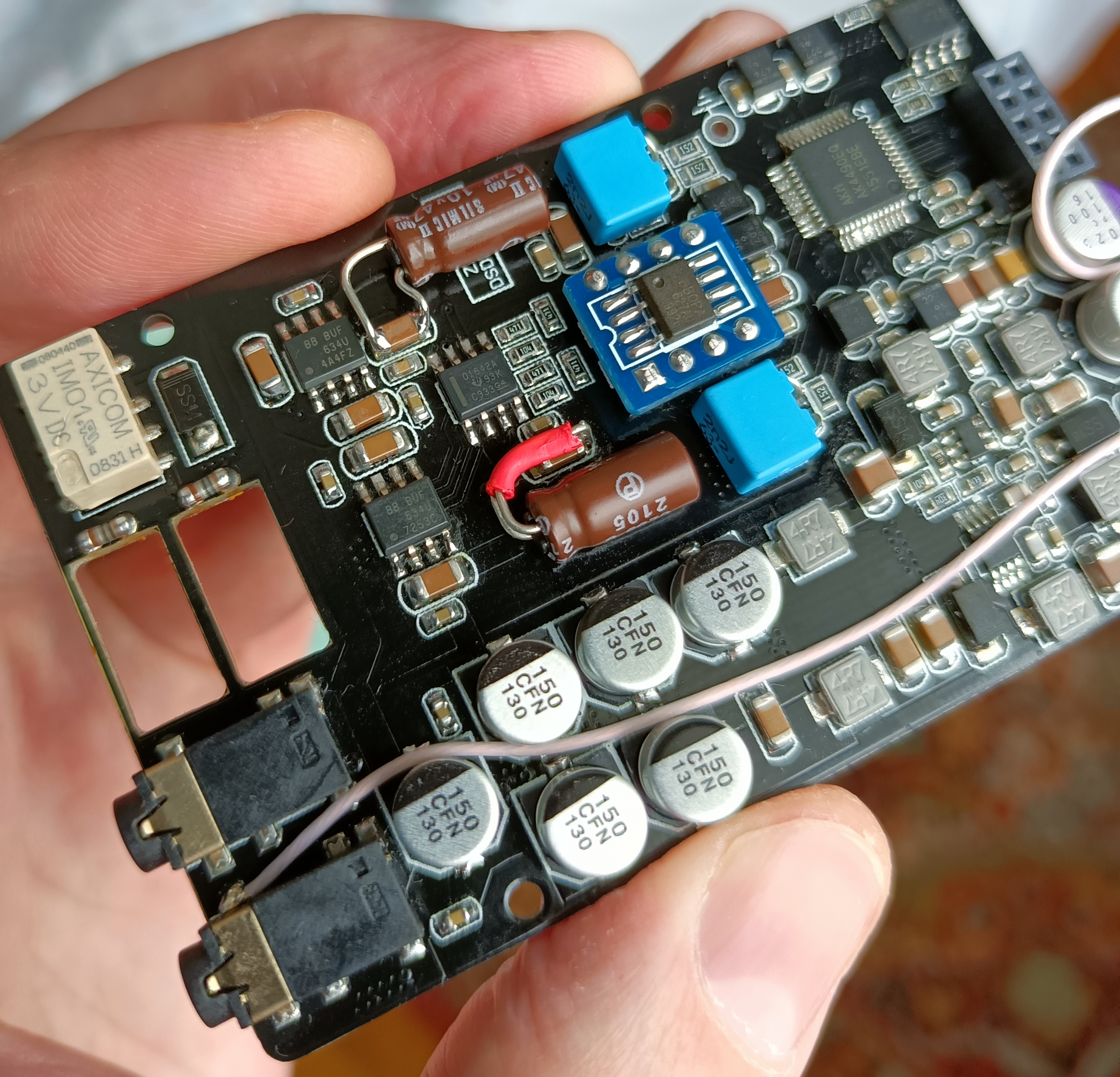
After a little use the stock DIP8 socket was loose and some of the opamp pins didn't make a good contact, I need to replaced it.
There are surface mount DIP sockets, but I don't have any, so I went and used the normal ones.
I have 2 different DIP8 plastic height sizes, if the taller plastic is used, only the DIP pins need to be broken (maybe sand a bit just in case), if the shorter plastic is used, the remaining pin needs to be a sanded (only sand the cone type transition to the larger pin socket, not further).
The shorter DIP8 will be a bit lower in PCB top and the contacts will go a bit further in the PCB bottom, I went with this one because this socket I had has better quality.
Here are the 2 plastic heights I have:
How the 2 height types fit the PCB bottom:
(top one only need to break the pins, bottom one need to be sanded)
Note:
The pins and solder need to be hidden bellow the PCB line, so they don't perforate or scratch the battery. Also further smooth the bottom PCB surface by sticking some kapton tape to that PCB bottom area.
If you take a Dremel bit, or a sharp X-Acto knife, and trim the plastic on the inside middle edges of the socket, then the low profile Dual Mono SOIC to DIP-8 adapters (without shoulders on the pins) will insert further (since the bottom chip will slip between the edges), allowing them to be no taller than a standard DIP-8 op-amp chip.
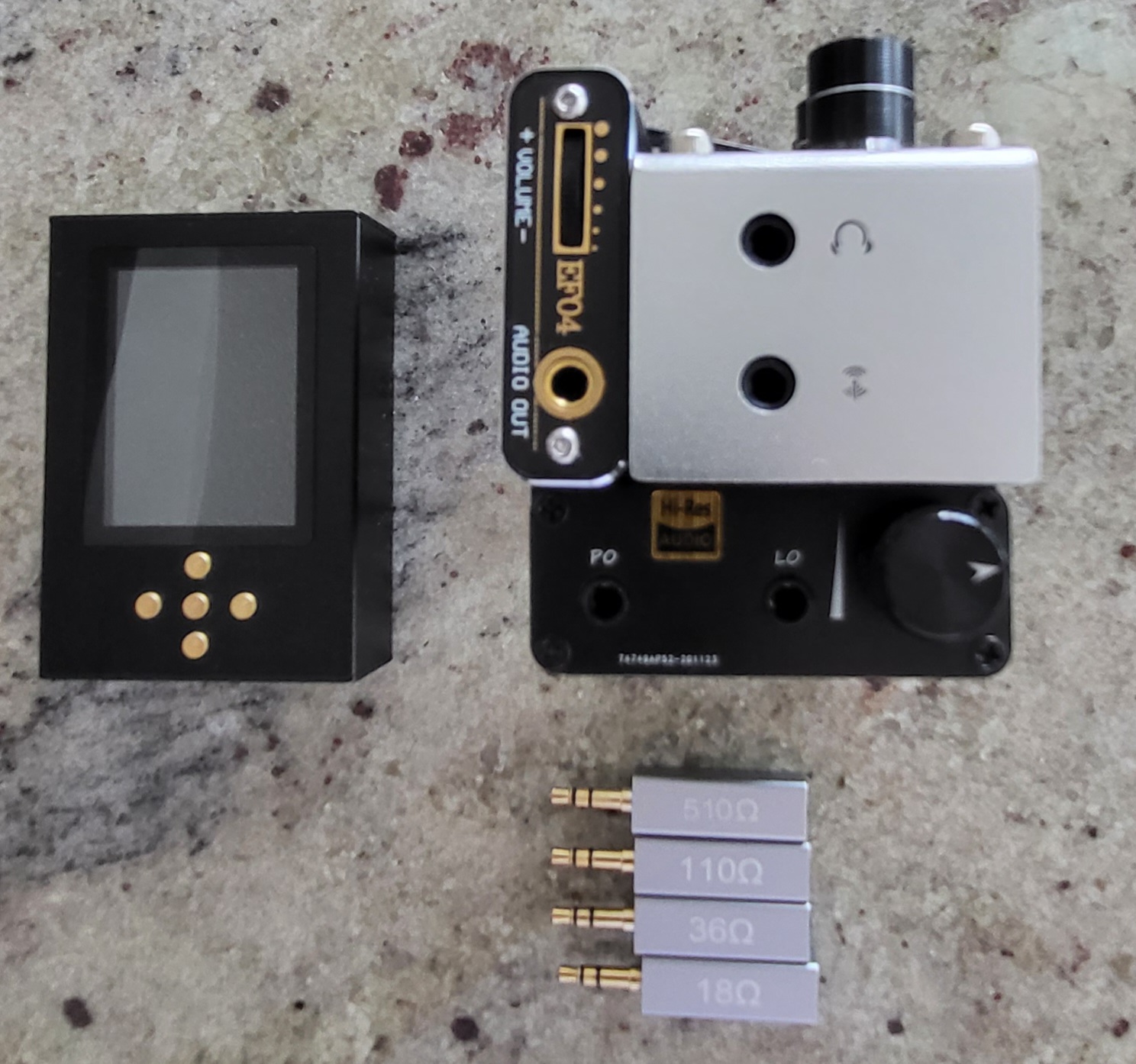
I tried my Burson V5i in the DSD last night. It sounded so good and robust with wonderful vocals and bass, that I decided to start the process of making the box bigger so I could fit it in. Dremel where are you!!!
If you take a Dremel bit, or a sharp X-Acto knife, and trim the plastic on the inside middle edges of the socket, then the low profile Dual Mono SOIC to DIP-8 adapters (without shoulders on the pins) will insert further (since the bottom chip will slip between the edges), allowing them to be no taller than a standard DIP-8 op-amp chip.
Good tip, I don't have dual mono soic to dip8 to try, so I had lowered the inside a lot with a x-acto for dual soic to fit , but I forgot to increase the lateral inside space and thanks to your comment I now see I need to remove a bit of the inside laterals for the soic to fit bellow.
Good thing I haven't soldered it yet, now I'm going to sand the lateral inside plastic with a metal nail file.
I also gained an extra 1mm inside the dsd case with the lower profile dip8 socket.
At some point I considered soldering only the dip8 female pins without any plastic support.
Just installed 2 ada4637 (browndog style custom support: had to make it by myself since there is no room): compared to the original opamp it is simply FANTASTIC: instrument separation, clarity and soundstage jump to another level.
Very, very much recommended.
I think it also could be a good option to open V5i-D with a tool like a Dremel, remove the dip socket and solder new (modified) pins.
To me it looks like the pins are soldered directly into the Dip socket, so you have to remove those pins first.
See how it looks inside:
This site uses cookies to help personalise content, tailor your experience and to keep you logged in if you register.
By continuing to use this site, you are consenting to our use of cookies.


")


