The Zishan dsd's corner
Mar 5, 2019 at 8:08 AM Post #2,056 of 3,711
TPS73250 mod is rather simple and ideally done along with LP5907 mod.

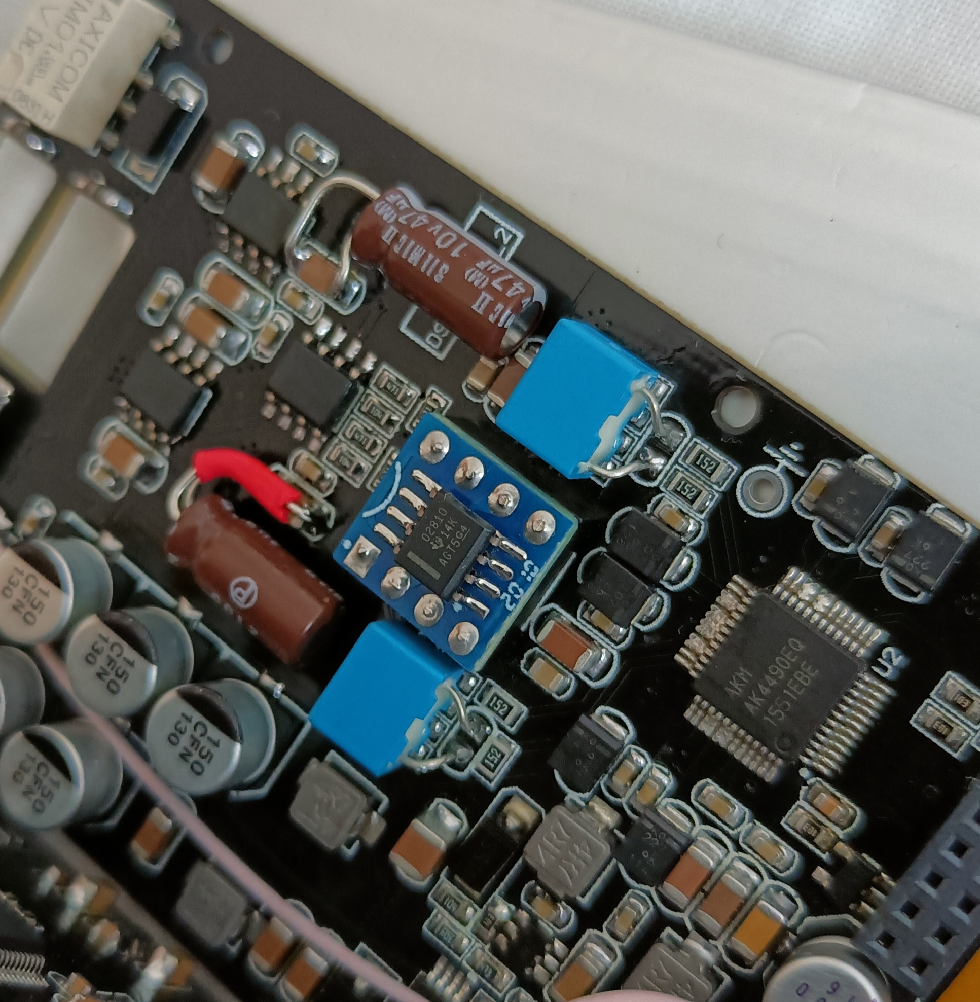
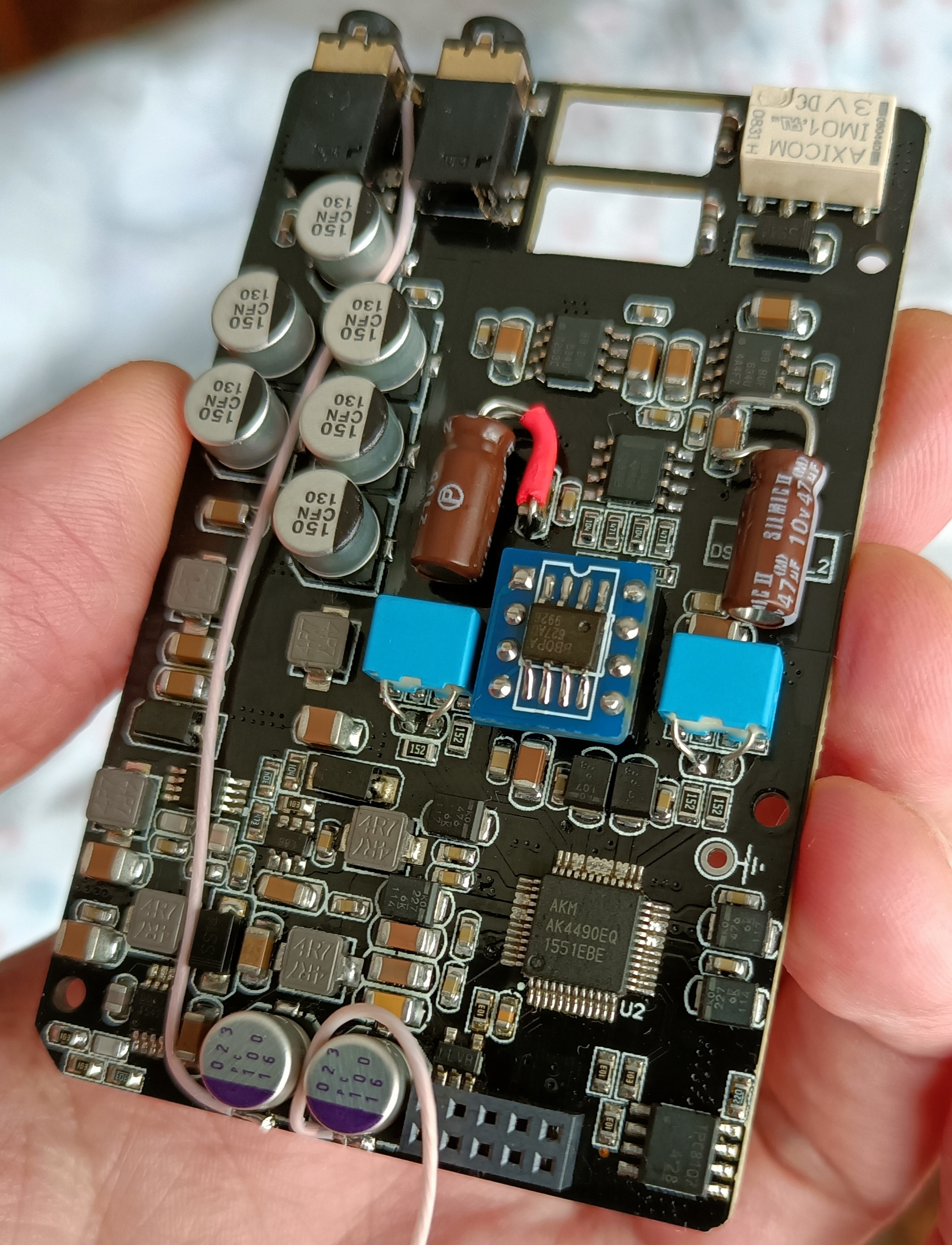
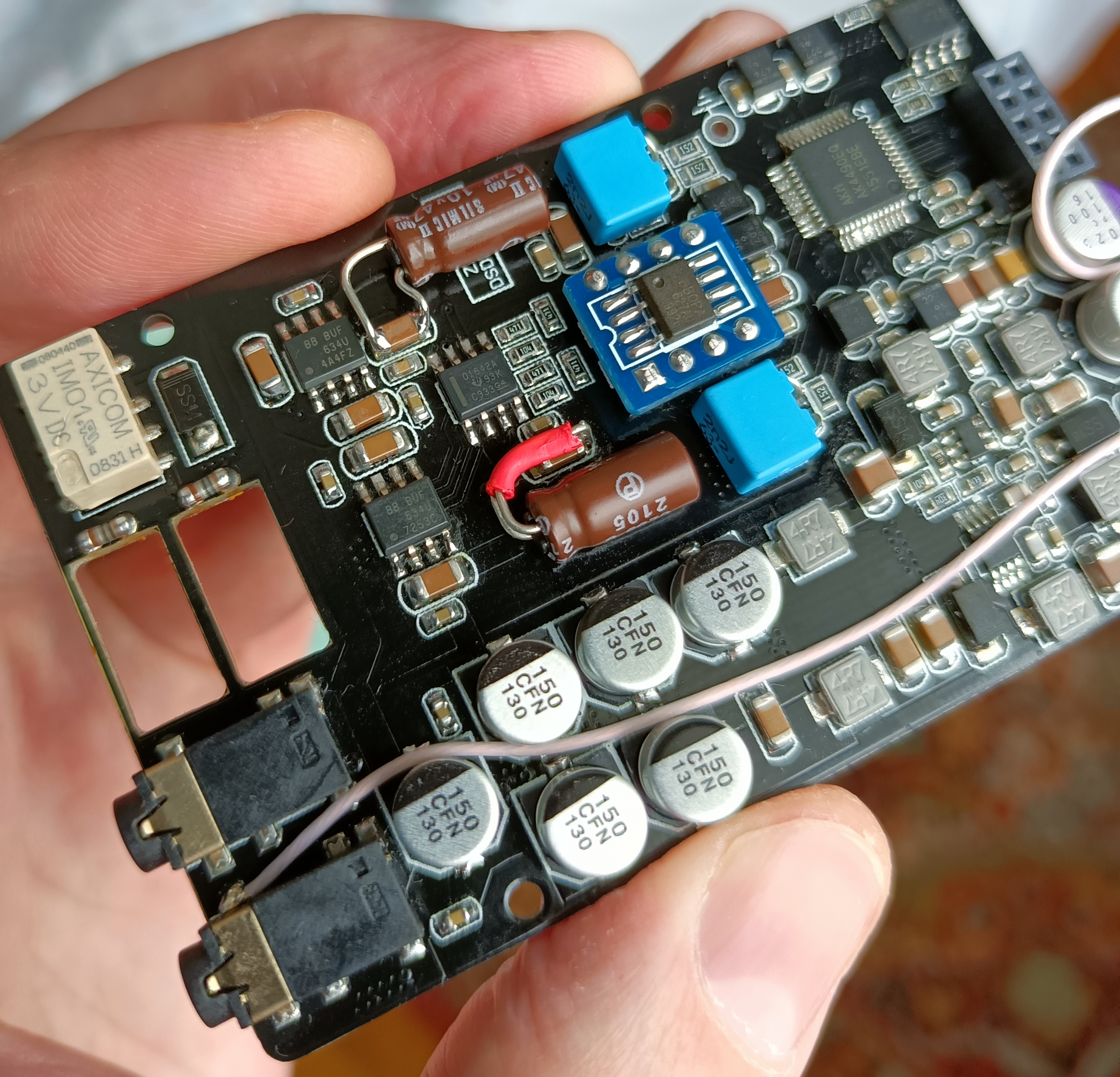
LP5907 replaces 5-pin sot-23 LDO at the right hand side of analog PCB below, improving DAC's 3.3V power supply.

TPS73250 replaces 5-pin sot-23 LDO slightly lower to the left of LP5907, improving DAC's 5V power supply.

These could be sourced from arrow.com provided it delivers to your country.

Hope it helps.

Zishan_DSD_22_R.jpg

I was wondering which power supply voltages come across the 10-Pin header from the Digital board / battery circuit?
 
Mar 5, 2019 at 10:29 AM Post #2,057 of 3,711
Well, actually I was asking about the TPS73250 mod...

Sorry, I was replying to Ivan post, still the first TPS73250 mod is on those photos.

There are now 3 different LDO mods:

1. This replaces all LDOs in both boards, but you can only do the DAC board:
https://www.head-fi.org/threads/the-zishan-dsds-corner.826185/page-99#post-14711840

This is part of a photo Abartels posted (great detail) and I used to identifying the stock LDOs in the DAC board, you need to replace those with the new parts described in the link above:
STOCK LDOs.jpg


2. Ivan instructions to reduce TPS73250 noise:
https://www.head-fi.org/threads/the-zishan-dsds-corner.826185/page-137#post-14817219
I've followed Ivan instructions and soldered a 0.01uF size 603, it's the small cap in the center of the red circle:
cap.jpg

3. This separate TVDD and AVDD 3.3V power (adding another 3.3V LDO):
https://www.head-fi.org/threads/the-zishan-dsds-corner.826185/page-137#post-14816714
 
Last edited:
Mar 5, 2019 at 10:44 AM Post #2,058 of 3,711
What does seperating the tvdd avdd do? I can do it but curious what it does
 
Mar 5, 2019 at 12:02 PM Post #2,060 of 3,711
Mar 5, 2019 at 12:31 PM Post #2,062 of 3,711
@Themilkman46290
The AK DAC datasheet recommends separated power lines to all digital and analogue parts of the DAC to lower interference between them. For example digital control signals are on/off voltages, these circuit can cause noise to other circuits if power is shared. If power supply lines are separated the interference is minimized.

Zishan made a shortcut and uses the same 3.3V power supply line to feed two separated parts of the DAC.
The mod separates those lines, see AK datasheet page 95, the DAC pin64 TVDD and pin59 AVDD are separated, read the notes in that page. Searching those acronyms in the datasheet, will give an idea of what they are and do.

This is my limited understanding:
The ideal circuit would be separated power (transformers or batteries) for each of those power lines with linear power regulators, as we see in the not portable table DACs. No switching power, no shared power lines.

Here we don't have space and we can't waste battery. So Zishan and other portable devices, use DC-DC switching voltage converters that are power efficient (don't waste power) but generate noise. Then they use LDOs, these are linear power regulators, that don't waste much energy because the supply voltage is very close to the output voltage. Zishan doesn't use LDOs to the opamps, only to the DAC.

We still have noise from the DC-DC converter.

This is a compromise, because if we used a high voltage battery like 7V or 9V or more and we use only linear voltage regulators, to make all the voltage levels we need, that would be the ideal no noise, but that would waste much energy, because some of the output voltages we need are very far from the battery voltage and linear converters dissipate all the excess voltage, if the voltage difference is big they need to dissipate a lot of power and waste that energy. The battery would run out very fast.

If they used one different battery for each voltage level, the DC-DC converts were not needed, but that takes space, adds complexity and cost, so compromises are made.
 
Last edited:
Mar 5, 2019 at 8:34 PM Post #2,063 of 3,711
I've verified that the Burson V6 Classic op-amps sound good driving the Balanced output on my iBasso PB2 Amp.
.
Looking forward to trying them as the LPF / Balanced output drivers, when I get to that point in modifying my DSD.
.
IMG_20190305_115804.jpg
 
Mar 6, 2019 at 3:47 AM Post #2,065 of 3,711
Ok
 
Mar 6, 2019 at 6:45 AM Post #2,066 of 3,711
I only tried mine in USB DAC mode once [...] What works [...] power off, connect microusb cable to Z1, power on [...]
any idea how to mod the Zishan Z1 to go straight into DAC mode when plugged out and in? I'm willing to open it up and solder around in it. It's super annoying, my USB ports are old, so I have to reach to the back of the PC about ten times a day to do this.
 
Mar 6, 2019 at 8:33 AM Post #2,067 of 3,711
I'm not sure if I can help.
The text you quote works for me.

If you can't try another computer, can you try a USB HUB?
A usb HUB will have another USB chip to interact with Z1.

You have mid/full tower computer?
Why not a permanent microusb cable from the computer to the top of the desk?
Then you only connect the microusb part to Z1.

Does this work?
-computer on
-usb cable always connected to PC, but not to Z1
-Z1 power off
-connect microusb to Z1
-turn z1 on

In other tests you make, try to leave USB cable always connected to the PC side and only disconnect/connect the microusb in Z1 to see if that helps.

I didn't understood exactly how you wanted it to work, please describe it.
 
Last edited:
Mar 7, 2019 at 4:03 PM Post #2,068 of 3,711
Take everything with a Grain of Salt and See the Big Picture.


(Any mod you make may or may not require re-circuiting the terminals to make up for shortcuts made by the Zishans’ makers. Regardless even without the reworking mods any genuine part properly cross reference on this thread or others will improve your sound. Some not all re-circuitry with its attempts to separate the LDOs “noise” will most likely have little to no effects on your audio sound nor improving “crossfeed” to your Zishan Sound. Therefore, these mods could be an unnecessary step that could damage your board permanently which has happen even to the best of them! )


I suspect with my stock LDOs and oscillator(s) that at times requires my Zishan at least 20 minutes to sound good.


Changing the LDOs and re-circuiting them to closely match Ak4497 Datasheet specs requirements makes sense on a practical level and I would imagine as a byproduct the overall power supply, battery charging, USB DAC, less harshness in sound, better defined via stock Digital Filters.


(For me knowing the basic electrical problems on the Zishan is a means to an end; In Layman’s Terms, I just want my player to sound more musical not solve all of its electrical problems nor impress anyone with mods that may or may not do anything to the sound)


It would be great if when discussing the theoretical “noise” it would better on the circuitboard and how it relates tangibly to actual Audible sound you are actually hearing from your music? For instance is there an noticeable noise on all your files coming from your Zishan when playing music files? Or is it just some of your files?? Please be specific by cross referencing different musical tracks to see if it’s constant in certain frequencies. This way the forum gets practical feedback not Theoretical noise.


On the positive side in reading through the thread in recent posts. There are practical consensus being built which in turn will lead to better improvements for better broad spectrum feedback.


Can anyone on this thread locate this LDO SANYO or something similar on Arrow or any authorized genuine part cross reference. And why can’t you simply convert DC to DC with 3.3 v to 9v LDO. If it’s a question of space and re-circuiting the LDO, I may have found a solution to that so just need to know they answer if it’s possible! Thanks!


Dithering is the process of adding high frequency white noise to a digital signal in order to "fill in" the spaces between samples and "fill in" the spaces between the actual analog value and the rounded off digital value. While it's true that the human ear can't "hear" ultra-sonic noise, the effects of ultra-sonic noise can be sensed by the ear, just as infra-sonic ( below 20 Hz) sound can't be "heard", but can be sensed (felt) consciously and subconsciously by the ear and body.”


Since the Zishan is limited by is UI features, the best mod I have made is an “Off Zishan” Mod (besides changing the capacitors and op amps) is fixing my DSD files with via dithering.*


This will not only improve your Zishan DSD sound. You will be able to A/B Test in Real Time w/o having to open or reopen your Zishan with manual labor to hear instant feedback. My Zishan sounds great with less grainy tracks, more detail and depth and no harsh high frequencies other Zishan Users have experienced. I am now able to hear the stock Digital Filters with its cut off feature and I haven’t even made changes to the LDOs and oscillator yet!


If you are interested in learning more there is a lot of information on this on the Internet.


Good Luck and Happy Modding!
 
Mar 7, 2019 at 4:28 PM Post #2,069 of 3,711
This is the buffer configuration of OPA 1622 that Ivan describes bellow.

I think this is only for people that want to experiment with electronics and with the player, because replacing the discrete transistors with this or any other opamp buffer, will require a major modification: all discrete components that are part of the discrete transistors circuit need to be lifted and if we think a bit about that and we see that Ivan didn't stop there, he replaced all the analog amplification. So if you start doing this, maybe you end up like his PCB. :)
I think this Matrix quote applies to the mods Ivan did:
After this, there is no turning back. You take the blue pill—the story ends, you wake up in your bed and believe whatever you want to believe. You take the red pill—you stay in Wonderland, and I show you how deep the rabbit hole goes.

Absolutely!
This massively improves the sound.
This could be done by tapping into DIP-8 socketed opamp's outputs, connecting OPA1622 outputs to output capacitors (lifting their positive terminals from PCB to disconnect them from the discrete buffer) and bridging 22ohm output resistors near 3.5mm socket. To configure OPA1622 as a buffer bridge 1-2 and 6-7 on its DIP8 PCB.
That's the simplest and easiest way to achieve it, will try to post visual guide before the end of the week.

I configured 1622 as a buffer (see above), added extra 22uF caps on rails (these replace 2 resistors on the top), added delayed start to the enable pin. These mods require ground connection wire though.

I've configured 1622 as a buffer per your instructions, I also read the datasheet to get the pinout and all makes sense, but could you please take a look at my photos and see if I did it right?

Maybe the photos are useful with your instructions, so I post them here.

Top side with the "bridge 1-2 and 6-7" and "extra 22uF caps", I didn't had 22uF, so I used 10uF.
(I used zero ohm resistor bridge, but a wire or solder can do the same job)
IMG_20190306_231427.jpg

Back side, here I replaced this two 1uF capacitors with 0.1uF, they are in parallel with the top side capacitors.
IMG_20190306_231503.jpg

The buffer pins are:
IMG_20190307_165131.jpg

IMG_20190307_172921.jpg

I used another dip8 opamp layout to identify the dip8 PCB pins and the wire colors:
DIP8-Colors.jpg
 
Last edited:
Mar 7, 2019 at 9:32 PM Post #2,070 of 3,711
@Merlin-PT , your implementation looks textbook, much better than my attempts/experiments!
Few comments if you don’t mind?
Output resistors should be jumped (ideally using 0ohm 0603 resistors similar to those you used.
Output caps may stay, then buffers outputs should be soldered on their positive legs.
I disagree that discrete output buffer should be desoldered/components removed, an easy way to make opa1622 output mod fully reversible is to solder inputs to 22Ohm resistors around socketed opamp top and lift output caps positive terminals, disconnecting them from the pcb (and thus from the output discrete stock buffer). The output resistors still need to be jumped, I’m afraid :frowning2:
 

Users who are viewing this thread

Back
Top