


Ivan TT
500+ Head-Fier
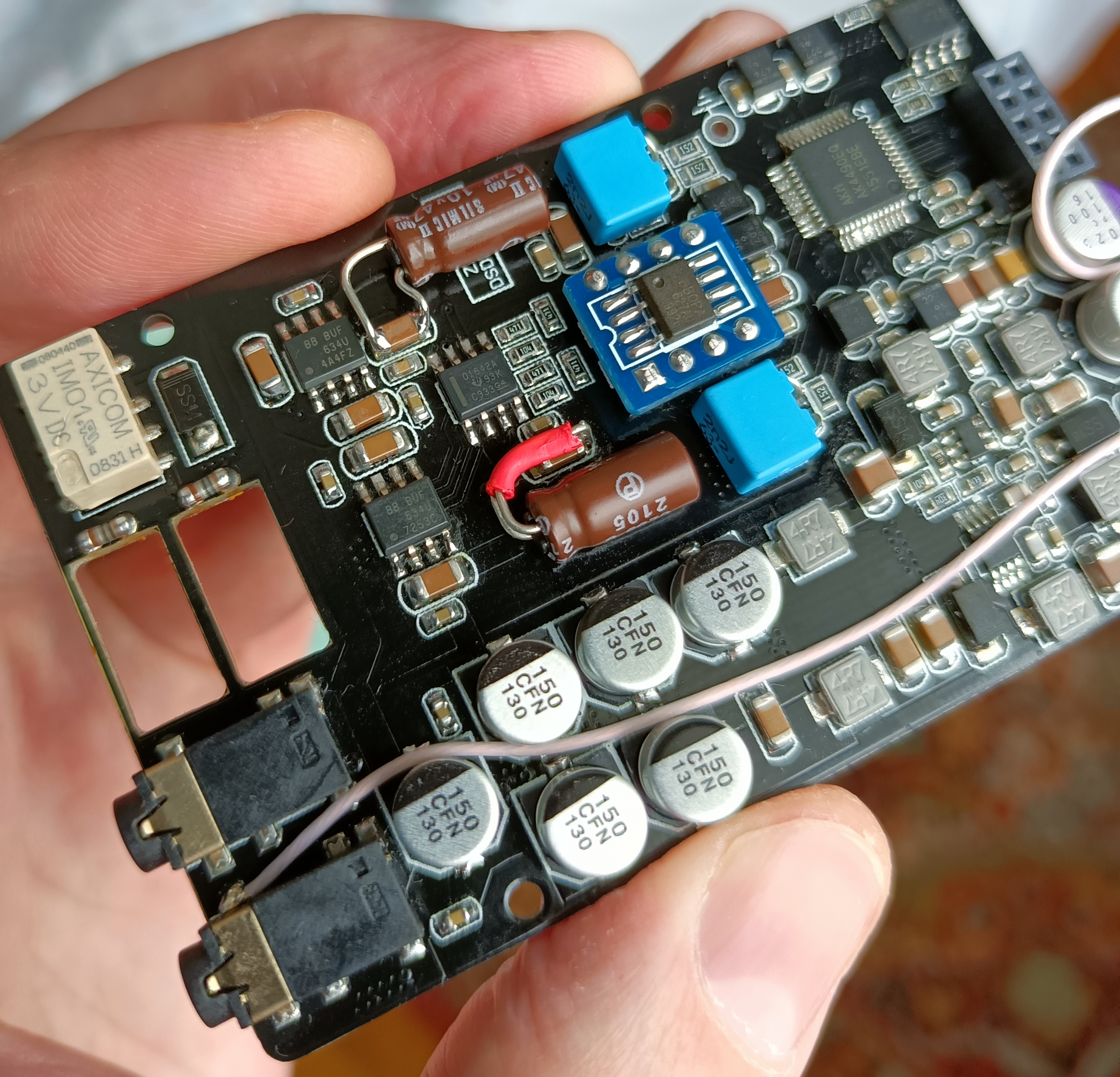
For the reference:I don't know if all those are in the audio path, or if they are part of the power circuit.

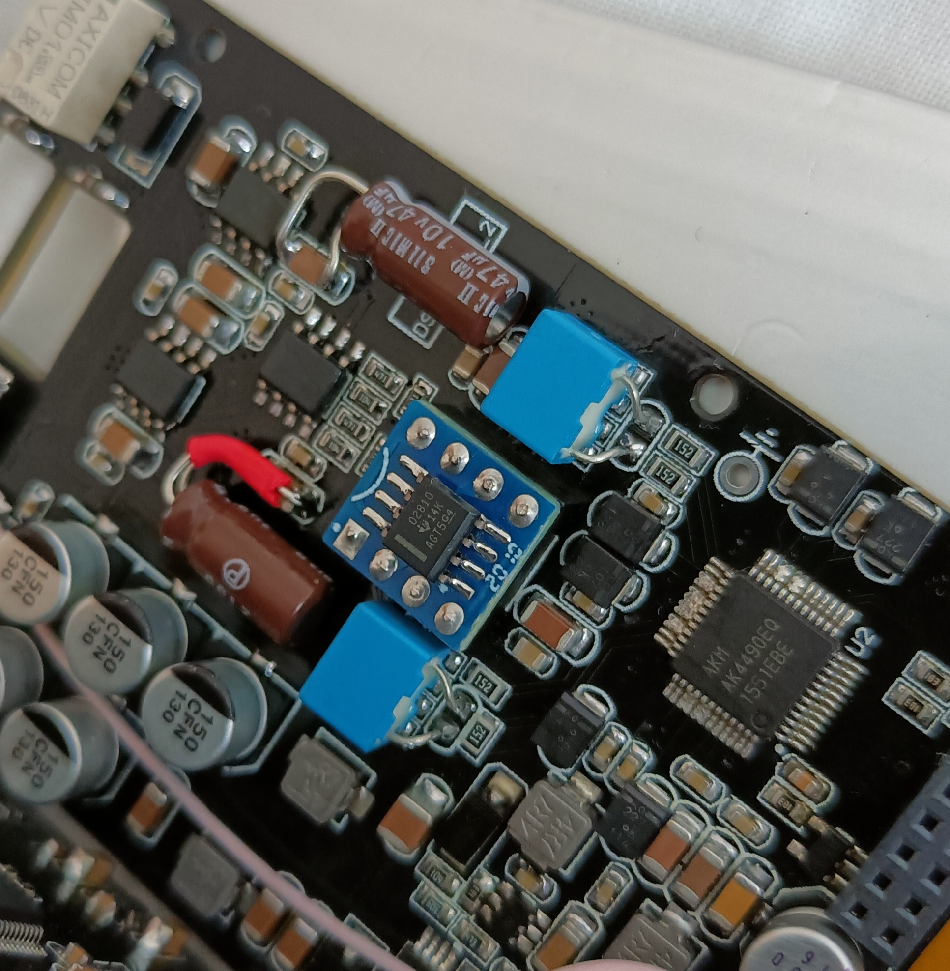
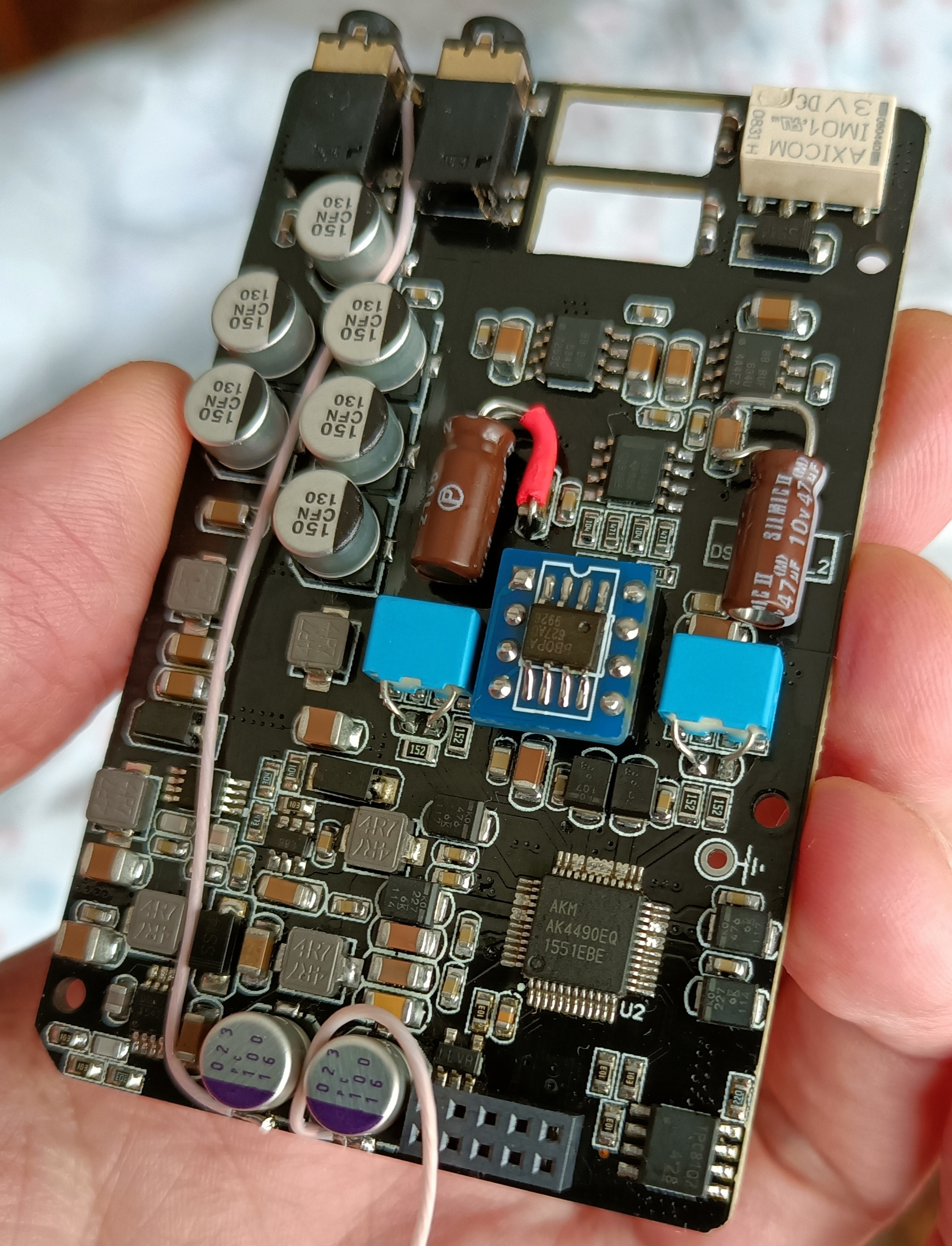
Audio input caps: 100uF or more, 6.3V (or more), 6.3x11mm (or thereabouts) - remove DC from DACs outs (which is present there by design).
Audio output caps: 220uF or more, 10V (or more), size - not sure - remove DC from audio amp's output AKA "protection" caps protecting earphones from the damage induced by DC that could be introduced by opamps swapping or mods (e.g. one of +/- power rails disconnecting). Earphones resistance + output resistors + capacitance form a High Pass Filter, increasing capacitance MAY improve low frequency response (stock resistors + 220uF caps + 32Ohm earphones give cutoff frequency of 13Hz).
Power caps caps: I would not worry about them, actually. But if there's an itch to replace them I believe EEEFT1C221AP would be a good choice.
Last edited:

") That’s my two cents anyway...
That’s my two cents anyway...

