The Zishan dsd's corner
Apr 11, 2019 at 5:01 PM Post #2,311 of 3,711
Alot of people are recommending the opa1622

I decided to order it for now, found it locally for about $10 second hand, guess I will give it a try for now. Maybe I will try the 627 a bit later, I am looking for something a bit more laid back for the 3.5 so I guess I will wait a bit longer and order a muses02 and see how I like that, I have been curious about it for a wile

You say out of the opamps that fit, what's your favorite that doesn't fit?

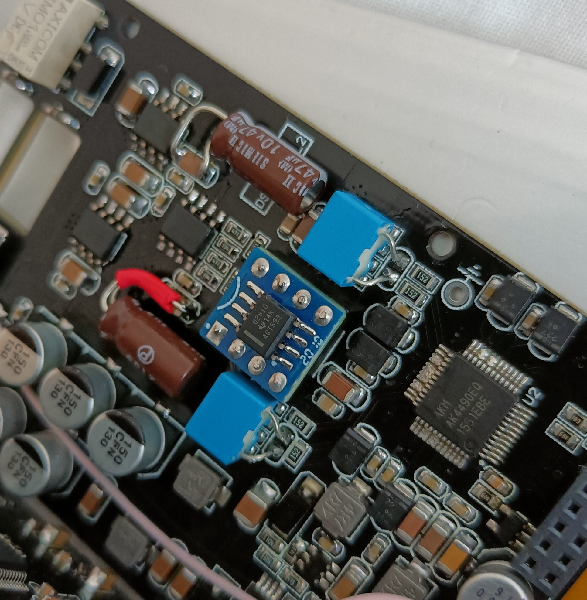
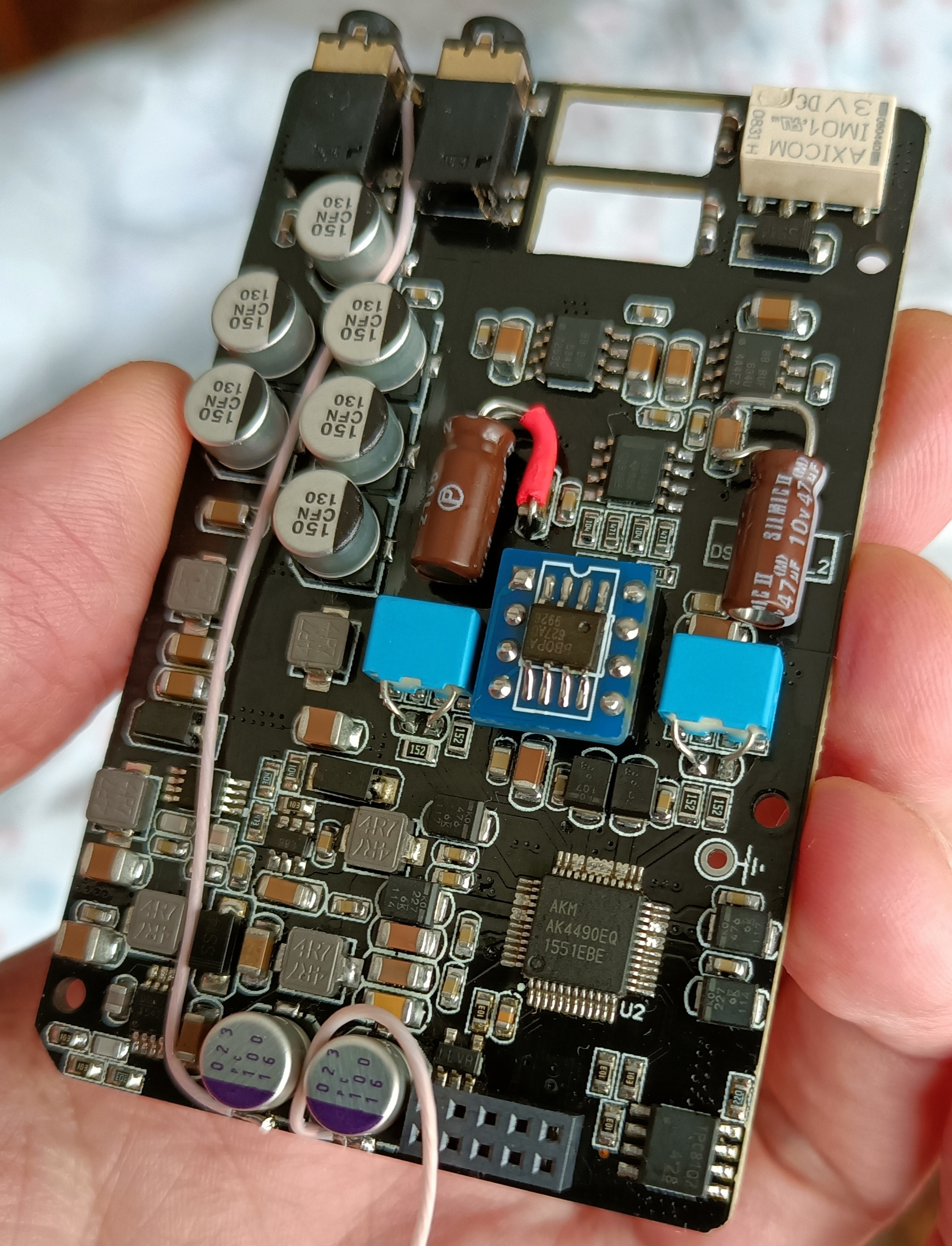
Well, once I re-house the DSD, I should be able to use any of the discrete op-amps, like the Sparkos SS3602, Burson V6 Classic, and Burson V5i-D - since the sockets will be moved to beside the circuit cards, rather than between them.
 
Apr 11, 2019 at 5:03 PM Post #2,312 of 3,711
How are those sparkos against the v5i?
 
Apr 11, 2019 at 5:15 PM Post #2,313 of 3,711
How are those sparkos against the v5i?

I haven't used either in the DSD - but in the Walnut F1 (one op-amp, before the phase splitter that drives the Balanced Output) and iBasso PB2 (two op-amps, driving the Balanced Output), the sound from the Sparkos seems like it's coming from a deeper, blacker background, with a more open Sound Stage, and having more detailed Bass, than the V5i-D. The V6 Classic sounds a lot like the Sparkos SS3602.
 
Apr 17, 2019 at 8:52 PM Post #2,314 of 3,711
I'm going to try to add a LDO to regulate the opamps power supply.
I ordered TPS7A3901DSCT, a low noise (21uV), high PSRR (69dB), Negative/Positive LDO voltage regulator.
If possible I want to keep the zishan inductors and need a very small size LDO.
TPS7A3901 is a 10 pin (+EP), WSON EP 3x3mm chip and each pin is 0.18mm.
This will be a challenge to solder, because I'll try to solder all the circuit components on the back of the WSON chip (if I can, without a PCB) to make the circuit very small, so I ordered 1mm length resistors/caps to select the output +-12V, total 4 resistors and 7 caps.
https://www.ti.com/product/TPS7A39

I measured the current supplied to the opamps, I lifted the 2 power inductors that go to the power reserve caps, confirmed that all opamps power supply were only connected to the power reserve caps (they are) and connected 2 multimeters in series with the inductors and the caps.

Don't mind the opamps I have installed, it's only to measure the current.
2xAD8066 + AD8066 + opa1622 = ~45.2mA in each one of the positive and negative rails:
IMG_20190326_163341.jpg

2xAD8066 + opa1688 + opa1622 = ~35mA in each one of the positive and negative rails:
IMG_20190326_163612.jpg
Power supply is a bit less than +-12V.

Lowering the voltage to 9V, using high or low impedance earbuds or changing the volume, didn't change the above opamps power supply current more than 1 mA.
 
Last edited:
Apr 18, 2019 at 12:23 AM Post #2,316 of 3,711
I want to solder the circuit on back of the WSON10 chip without a PCB, but if I can't, plan B is to make or buy the PCB.

TPS7A3901DSCT, 1 unit - https://www.arrow.com/en/products/tps7a3901dsct/texas-instruments
R1P= 90.9K (for calculated +12V), 1 unit - https://www.arrow.com/en/products/tnpw040290k9beed/vishay
R1N= 100K (for calculated -11.9V), 1 unit - https://www.arrow.com/en/products/tnpw0402100kbyep/vishay
R2N=R2P= 10K, 2 units - https://www.arrow.com/en/products/tnpw040210k0beed/vishay
CFFP=CFFN=CNRSS= 0.1uF, 3 units - https://www.arrow.com/en/products/cl05b104jo5nnnc/samsung-electro-mechanics
CINN=CINP=COUTN=COUTP= 10uF, 4 units - https://www.arrow.com/en/products/cl21b106koqnnne/samsung-electro-mechanics

www.ti.com/lit/ds/symlink/tps7a39.pdf
Please read pages 25,26,27 of datasheet to confirm the component values I selected.
I always go with lowest possible price, so my caps are X7R and resistors 0.1%.
Sizes are 0402 and 0805 to try to solder on back of the chip.

Note:
I went with the recommended value in the datasheet table (pag.26) of 100K for a target value of -12V, but that has a calculated output of -11.9V in the same table, so maybe I don't exactly get -12V, but what I want most is the low noise, high PSRR. I think we need just a bit more than 100k for -12V. On the other hand, they say the recommended 90.9K gets precisely +12V.

EDIT:
The resistor values I posted above are recommended in the datasheet table and _approximated_ calculations for those values are:
VOUTP = VNR/SS × (1 + R1P / R2P)
VOUTN = VNR/SS × (–R1N / R2N)
From pag.6, VNR/SS = min=1.172V typ=1.19V max=1.208V
(note:"Substituting VNR/SS with VFBP on the positive channel and VNR/SS with VBUF on the negative channel gives a more accurate relationship")

VOUTP = 1.19 × (1 + 90.9/ 10) = +12.0071V
VOUTN = 1.19 × (–100 / 10) = -11.90V

In theory and with typical VNR/SS, we need to increase R1N a bit or decrease R2N a bit to get -VOUTN = VOUTP.

I've received the components, the chip is 3mmx3mm, it will be a nightmare to solder all the components on it's back without PCB. :)
 
Last edited:
Apr 20, 2019 at 7:08 PM Post #2,317 of 3,711
Soldering all the circuit components on the back of the TPS7A3901, was much more difficult than if I had used a PCB.
The photo doesn't make justice to the WSON10 3x3mm size.
With all the components soldered, it's so small it looks like something out of a movie and not real.
Wire is 0.2mm diameter and all other components are 1mm length, except the 4 bigger 10uF capacitors that are 2mm length.

I tested it and it's working well, it is also delivering the same current the opamps were using before.
I don't have anything with the accuracy required to measure the low noise (21uV), high PSRR (69dB).
As suspected, with the suggested datasheet resistor values, in my circuit and mutimeter, I got -11.87V and +11.98V, but it's easy to adjust 1 resistor value to give precise -11.98V, still this doesn't affect low noise, high PSRR.

tps7a3901-01.jpg


tps7a3901-02.jpg

It's installed in the lower part of this photo.
I managed to keep the 2 inductors.
The right inductor, is sideways and only his right pad is soldered to the PCB, the left pad is soldered to the LDO positive input.
The left inductor is lifted in the air and makes ~20º with the PCB, only the bottom pad is soldered to the PCB, the upper pad is lifted above the diodes and connects to the LDO negative input.
LDO outputs, (-) GND (+), are the wires to the 3 bottom PCB pads.
 
Last edited:
Apr 20, 2019 at 7:28 PM Post #2,318 of 3,711
If anyone is interested...I got the Z3 with the AK4493 in it and I like it. I think the chip makes a good difference to the 4490. The 4493 version is more detailed and brings up some of the sounds in the recording so you can hear more. Consequently, it makes some of the opamps that I passed on with 4490, better sounding. That’s just a general assessment. I’m not really even thinking about modding the 4493.
 
Apr 20, 2019 at 8:04 PM Post #2,319 of 3,711
Soldering all the circuit components on the back of the TPS7A3901, was much more difficult than if I had used a PCB.
The photo doesn't make justice to the WSON10 3x3mm size.
With all the components soldered, it's so small it looks like something out of a movie and not real.
Wire is 0.2mm diameter and all other components are 1mm length, except the 4 bigger 10uF capacitors that are 2mm length.

I tested it and it's working well, it is also delivering the same current the opamps were using before.
I don't have anything with the accuracy required to measure the low noise (21uV), high PSRR (69dB).
As suspected, with the suggested datasheet resistor values, in my circuit and mutimeter, I got -11.87V and +11.98V, but it's easy to adjust 1 resistor value to give precise -11.98V, still this doesn't affect low noise, high PSRR.


It's installed in the lower part of this photo.
I managed to keep the 2 inductors.
The right inductor, is sideways and only his right pad is soldered to the PCB, the left pad is soldered to the LDO positive input.
The left inductor is lifted in the air and makes ~20º with the PCB, only the bottom pad is soldered to the PCB, the upper pad is lifted above the diodes and connects to the LDO negative input.
LDO outputs, (-) GND (+), are the wires to the 3 bottom PCB pads.

:astonished:

Do you have a microscope :microscope:, or just a magnifying visor?
 
Apr 20, 2019 at 8:52 PM Post #2,320 of 3,711
I wish I had one, I did the soldering only using eyes and 1mm JBC tip + JBC flux.
It was a nightmare to solder this small size, some solder points needed more than 1 try to get it right.
I had to plan it all before soldering, too much iron time and all the the other components could fall.
I used only this to inspect connections after each solder (and a multimeter to also test continuity/shorts):
https://www.aliexpress.com/item/60X...o-Camera-Clip-LED-Lenses-For/32705459182.html
(I use it without the phone to inspect the soldering, with the phone only to take some photos, it's not very good, but it's better than nothing)
tps7a3901-03.jpg

It's better than in the photo, but you can have an idea of the magnification.
All my photos are with nexus 5 phone that is at hand, quality is so so.
 
Last edited:
Apr 20, 2019 at 9:59 PM Post #2,321 of 3,711
I wish I had one, I did the soldering only using eyes and 1mm JBC tip + JBC flux.
It was a nightmare to solder this small size, some solder points needed more than 1 try to get it right.
I had to plan it all before soldering, too much iron time and all the the other components could fall.
I used only this to inspect connections after each solder (and a multimeter to also test continuity/shorts):
https://www.aliexpress.com/item/60X...o-Camera-Clip-LED-Lenses-For/32705459182.html
(I use it without the phone to inspect the soldering, with the phone only to take some photos, it's not very good, but it's better than nothing)

It's better than in the photo, but you can have an idea of the magnification.
All my photos are with nexus 5 phone that is at hand, quality is so so.

That's a neat little clip-on cellphone camera magnifying lens.

I recently bought one of these magnifying visors (1x to 14x), with removable LED light, for $22 from Amazon.
It's got two slots to insert the lenses, plus the little swing-out lens that adds extra magnification to the right eye.
https://smile.amazon.com/gp/product/B07BF7Y7K3/
 
Apr 20, 2019 at 10:23 PM Post #2,322 of 3,711
Soldering all the circuit components on the back of the TPS7A3901, was much more difficult than if I had used a PCB.
The photo doesn't make justice to the WSON10 3x3mm size.
With all the components soldered, it's so small it looks like something out of a movie and not real.
Wire is 0.2mm diameter and all other components are 1mm length, except the 4 bigger 10uF capacitors that are 2mm length.

I tested it and it's working well, it is also delivering the same current the opamps were using before.
I don't have anything with the accuracy required to measure the low noise (21uV), high PSRR (69dB).
As suspected, with the suggested datasheet resistor values, in my circuit and mutimeter, I got -11.87V and +11.98V, but it's easy to adjust 1 resistor value to give precise -11.98V, still this doesn't affect low noise, high PSRR.


It's installed in the lower part of this photo.
I managed to keep the 2 inductors.
The right inductor, is sideways and only his right pad is soldered to the PCB, the left pad is soldered to the LDO positive input.
The left inductor is lifted in the air and makes ~20º with the PCB, only the bottom pad is soldered to the PCB, the upper pad is lifted above the diodes and connects to the LDO negative input.
LDO outputs, (-) GND (+), are the wires to the 3 bottom PCB pads.
This is absolutely awesome!
What was the effect on the sound?
 
Apr 20, 2019 at 10:43 PM Post #2,324 of 3,711
After all the trouble, I was afraid if it sounded worst, but prepared to not use it if it was the case. I had it mounted in some wires, to do tests, before I solder it to the final position.
The difference is _subtle_ but audible, it sounds cleaner with more detail.
 
Last edited:

Users who are viewing this thread

Back
Top