Quote:
Originally Posted by spritzer /img/forum/go_quote.gif
Any and all picture would be very helpful to troubleshoot this.
|
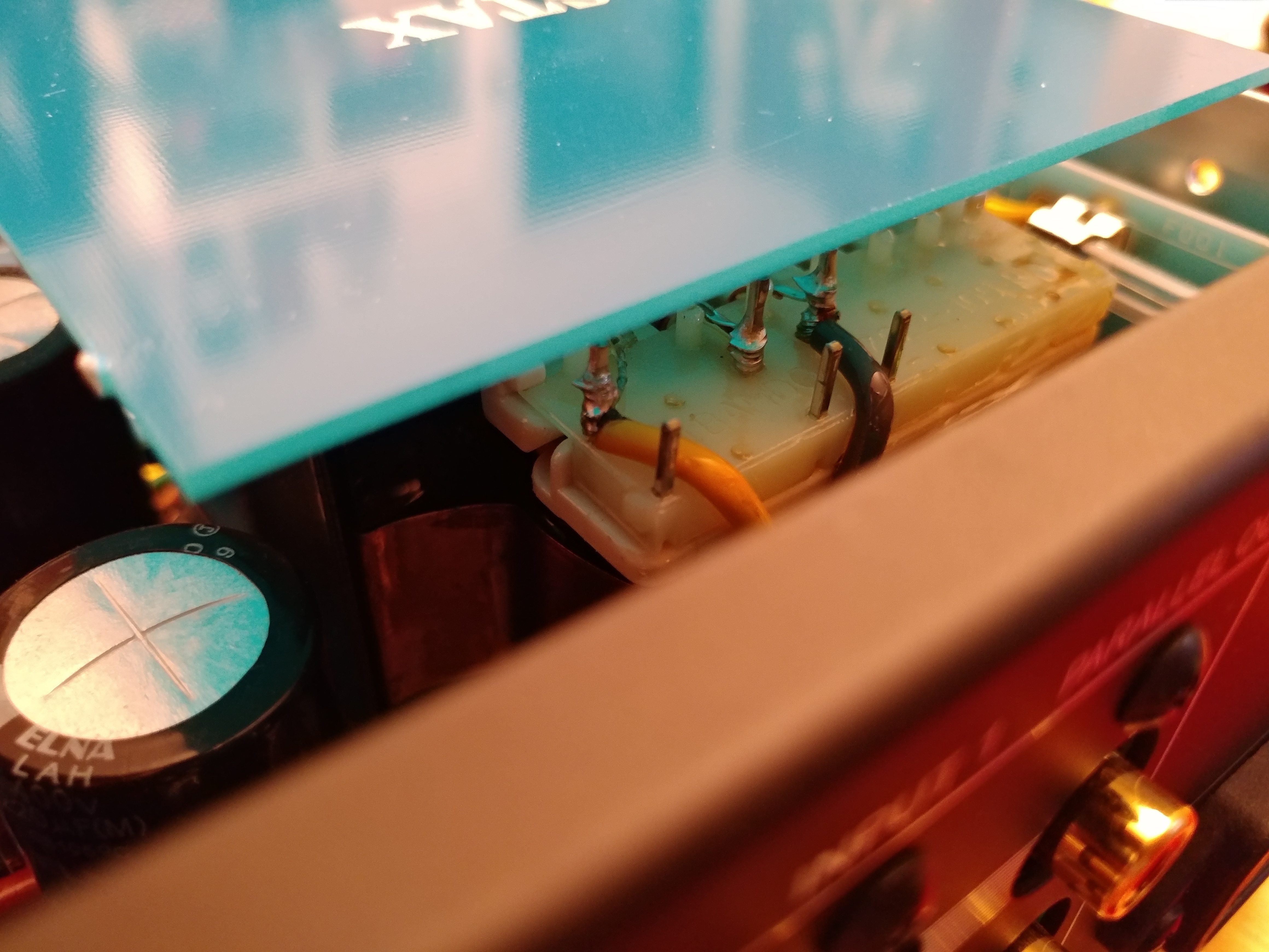
There are several pictures in some previous posts, but perhaps they don't show enough detail. I'll try to do some macro shots w/ the drivers assembled w/o damping material tonight.
Quote:
| You can take a peek inside the driver and then clamp it together again and the glue should hold. It did so with my ESP6 and I did it numerous times to find the right spot for the replacement drivers. You could also measure the driver to see if there are any shorts inside it. |
Yeah, that should be fairly easy. I'm guessing there shouldn't be an electrical connection between any two posts, right?
Does anybody know or have a simple diagram of the correct hookup of the esp9? If they have been tampered with, maybe the boards in the earcups aren't wired properly. I've been very careful to reassemble exactly the way they are in my pictures from the initial disassembly, but if that isn't correct . . .
Edit: Oh, and 600-volt bias sounds unlikely to me. The 0.1uf cap in the left earcup is probably for bias voltage, and it's only rated at 500 volts.
I'd offer to measure, but my set is highly questionable.
The ESP-950 is said to have 600v bias, which is touted to be the highest bias voltage out there. Couldn't possibly be true unless they are only referring to current production. Aren't some of the jecklins 900v?