


palchiu
500+ Head-Fier
- Joined
- Dec 30, 2004
- Posts
- 643
- Likes
- 24
Quote:
Like this pic?

pics from 007ta should be same.
Hi
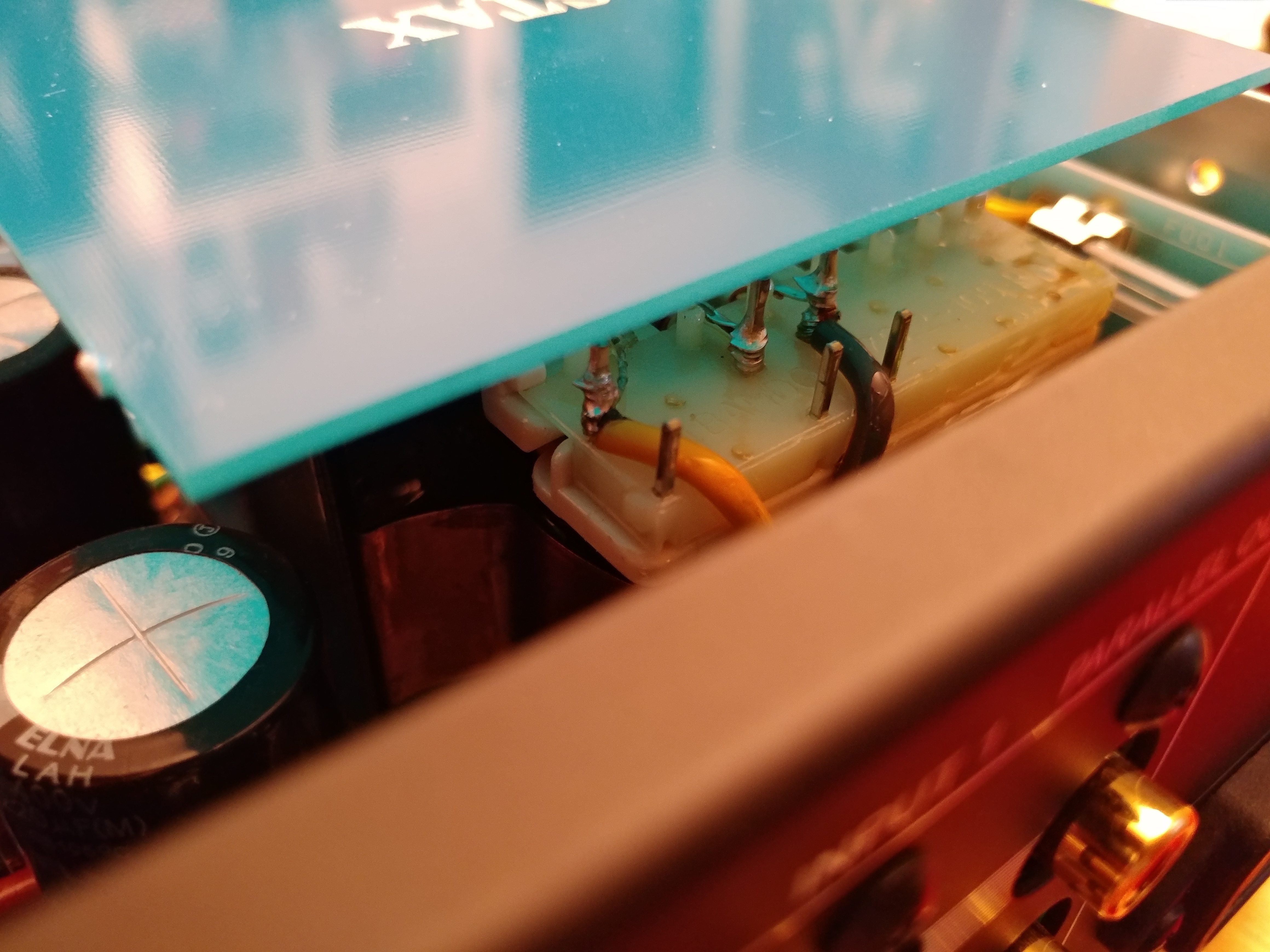
I just opened and removed the fuse-board.
I discovered that on metal-bar 2 and 5 there is no wire soldered to...
I think I have to go deeper.
Helpful if I would know about the windings on the primary side:
There are the following wire-colors, from left to right (see picture):
a) yellow
b) white
c) green
d) no wire attached to the copper-color wire coming out of transformer
e) grey
f) brown
g) no wire attached to the copper-color wire coming out of transformer
would be helpful to have a schematic.
I read there are two 0-100V-110V windings. Which colors are what?
Peter
Like this pic?
pics from 007ta should be same.
 )
)![size]](http://files.head-fi.org/images/smilies/ph34r.gif[size=13px][/size])
