If it wasn't for the sole fact that fiberglass are sold in such big vats I would have tried it already! haha.
May as well dump the rest in my attic for extra insulation...
@jgray: while I don't recall ever having recessed mids relative to bass and trebles when stacking, it made them sibilant IME. Perhaps my ears felt more comfortable but my ear drums shriek in pain after 20 minutes.
Well, one of my headphone still uses stacked pads but no sibiliance there. It's supra-aural though. And kinda uncomfortable.
Measuring headphones is way easier than I have expected! REW is a very straightforward tool, no need to wander around in menus.
One word of warning though. I use en EM-9767 mic, probably not as good as WM 61A, but there shouldn't be any principal difference.
I have soldered the mic, plugged it into soundcard, and it worked immediately. Quiet and somewhat dull sound, but I thought it was normal without amplifier. Then I ran tests on headphone, and there was wild, more than 20dB, fall-off after 2kHz. Tried to EQ that, but sound was no way natural at all.
Then I wanted to turn the mic off so it doesn't interfere with music and went into Windows sound settings. Appeared that I didn't check the "+20dB mic boost" option, enabled it, and.. Not only loudness boost, but now it picked high frequencies normally. Ran tests, and the fall-off was mostly gone. There is still some, but I'm sure it's now more due to the headphones than the mic. Then I read on some forum that the "mic boost" is actually phantom power, and these mics indeed work without it, albeit poorly. But soundcard's power supplies aren't good as well, they cut off HF. Realtek sound cuts at 12kHz, Creative Audigy at 14-15 kHz, so it is actually better to always use external phantom power and an line in instead of mic in.
There are graphs of my current T20RPs. Blue with 3 2/3 bass ports closed, green with port additionally closed over by finger, so almost completely shut. Tried to EQ this is player, sound was a bit strange (probably due to low quality stock fb2k EQ), but indeed more natural in some places. Lots of work ahead!
EDIT:
This is without any averaging. I have measured by BMF's suggested way, placing mic at ear canal entrance. Doesn't seem very convenient and repeatable to me, so I decided to use a flat styrofoam baffle and do 2 measurements on each run: one with naked baffle, one with baffle covered by acoustic foam - to search for ear-side reflections. The in-ear measurements aren't out of the question of course, but baffled seems to be more repeatable to me.
Which reminds me, BMF, is there any way to measure IEMs with that setup?
That's one thing I've been trying to figure out with my method... although as you may know there is no averaging capability nor anything other than a unbalanced FR reading.
I just get the feeling that placing the IEM on the mic just doesn't reflect proper measurements. Lack of seal maybe?
If it wasn't for the sole fact that fiberglass are sold in such big vats I would have tried it already! haha.
May as well dump the rest in my attic for extra insulation...
@jgray: while I don't recall ever having recessed mids relative to bass and trebles when stacking, it made them sibilant IME. Perhaps my ears felt more comfortable but my ear drums shriek in pain after 20 minutes.
Well, one of my headphone still uses stacked pads but no sibiliance there. It's supra-aural though. And kinda uncomfortable.
Hmm I see. Thanks for the input though, it's always good to receive other point of views and opinions. IMO re:supra-aural and stacked ear pads, maybe the thickness just becomes too thick and it turned into a clamp rather than providing comfort.
Does Sony sells parts of the XB700/500 separately? That tractor tire ear pads should probably do something drastic LOL. Hmm I'll try bug my friends if they have 1 or 2 busted.
Measuring headphones is way easier than I have expected! REW is a very straightforward tool, no need to wander around in menus.
Then I wanted to turn the mic off so it doesn't interfere with music and went into Windows sound settings. Appeared that I didn't check the "+20dB mic boost" option, enabled it, and.. Not only loudness boost, but now it picked high frequencies normally. Ran tests, and the fall-off was mostly gone. There is still some, but I'm sure it's now more due to the headphones than the mic. Then I read on some forum that the "mic boost" is actually phantom power, and these mics indeed work without it, albeit poorly. But soundcard's power supplies aren't good as well, they cut off HF. Realtek sound cuts at 12kHz, Creative Audigy at 14-15 kHz, so it is actually better to always use external phantom power and an line in instead of mic in.
Measuring headphones with REW is surprisingly painless.
One clarification I wanted to give - there is a difference between providing phantom power, and providing microphone preamplification. Preamplification is needed to bring a microphone output up to line level, whilst phantom power is needed for specific types of microphones, like condensers. These work in a similar way to electrostatic headphones, but backwards - they need a constant voltage bias in order to operate at all. I also want to give a warning at this point that there are two levels of phantom power that are usually used - 9V and 48V. When professional audio interfaces say 'phantom power', they nearly always mean 48V. This is probably bad news for an electret mic like the Panasonic WM61a. However, electrets mics will still require preamplification in addition to their phantom power, or their output level will be very low, and the signal to noise level will also be atrocious. I believe the microphone boost in windows handles both the 9V phantom power and the preamplification for most 'consumer' soundcards.
------------
[Apologies in advance for the rather long post - I wanted to get as many of my thoughts down in one post as possible]
In other news, I've been working with BMF over the last few months while he developed his latest set of mods (I've mostly been helping with the measurement and analysis side of things, so I can't claim much credit for modding innovation). However, there are a couple of fundamental differences between the mods I am running now and the mods that BMF has put forwards, not out of choice, but out of necessity. I thought I'd share.
Firstly, I had removed material from the ear-side of my stock T50RPs quite a while ago. The black felt over the driver was removed, leaving the driver square bare apart from the fine mesh over it. I had also removed the foam 'dust cover' on the Shure 840 pads. This means that there is almost no material between the driver and the ear apart from the magnets and that very fine mesh. I did this because I wanted to see if it would help to bring out the treble in the stock headphones, which are quite dark sounding.
It definitely brought out the treble, but not in an ideal way, and once the rest of the BMF mods were complete, it left an ugly spike at around 9kHz on the frequency response. I started experimenting with different materials to put earside in order to replace those two components that I removed, and I eventually settled on a square of microfibre cleaning cloth directly over the driver (cut exactly to fit the driver square, and taped down being careful not to block the baffle vents). Over this, I placed an oval of 'floppy' craft felt, 2mm thick, cut to the size of the baffle, and held in place just by the pads themselves.
Here's a graph showing the difference it makes on the frequency response:
The difference in the high frequency response is easily visible - which one you will prefer is up to you, but I personally find it much nicer to listen to with the replacements in place. There may also be a small difference through the 500Hz to 3kHz range, with the earside replacements bringing that down slightly to a flatter response. The difference is small enough though that you might chalk it up to just variation in placement of the headphones on my head. And although I didn't do many repeat measurements, it is my feeling that the difference in bass response is mostly due to headphone placement, and not to the change in ear-side mods, whereas the high frequency change has been consistent across multiple tests.
I briefly tried a sandwich of felt -> a thin slither of cotton wool -> felt, and it measured marginally better than my microfibre -> felt setup, but it was very thick and pressed against my ears somewhat uncomfortably. You may wish to try this one yourselves.
The second fundamental difference between my headphones and BMFs is in the white paper on the back of the driver. I have what we cautiously believe is the less porous paper. Because of this, in my mods, I do not apply material directly to the back of the driver paper. Applying a thin strip of porous plastic tape, one grid square wide, and 3 long, can bring the upper midrange up in level if you wish, and if you have the same driver paper as me.
A quick note of caution before I forget: I live in the UK, and bought some transpore off Amazon. It says 3M Transpore on the box, and on the inside of the roll of tape, but it is in fact not the same thing as BMF's transpore. It is much closer to what he calls micropore - a porous cloth based tape. This does not work at all in headphone mods. I bought a porous plastic tape from a sports first aid website instead - from pictures I've got, it looks identical to what BMF and the US market calls Transpore, though it has no brands printed on the inside of the roll.
If you have removed the ear-side material, or you have the more porous white paper and you wish to try BMF's mods, I suggest you give my variants a go too, which are included in the spoiler below. If you are not in this position, I would just go with BMF's mods straight up - his measure very slightly flatter than mine do, without the 1dB humps every now and again through the midrange.
CUPS
Newplast flush mass loaded in baffles
Stock cup vent felt in place (all vents open on the outside)
Acoustipack lite in cup floor wells (same as BMF)
Paxmate pyramids superglued on top of the Acoustipack (same as BMF)
Cotton on top (this needs to be tuned by hand - cotton varies in density from different companies, and it is very difficult to measure out accurately)
Stock white driver paper, with nothing stuck to it.
EARSIDE
Black felt removed over driver
All 4 baffle vents drilled out
Microfibre square over driver (careful not to cover baffle vents with it)
2mm thick floppy craft felt over that
Shure 840 pads with dustcover cut away
---------------------------
MEASUREMENTS
Being able to measure the headphones is very useful. Some things like measuring out equal amounts of cotton per cup can be very difficult, and getting the same cotton wool as someone else can be difficult in the first place. Whilst you could tune by ear and make the very strong argument that if you can't hear any difference, it doesn't matter, ultimately it is nice to be able to quantify what each mod is doing. So, I'm going to post some measurements I've taken recently, of my finished mod (in the spoiler above), and a couple of other headphones I own to give a reference point - hopefully ones some of you will be familiar with. I'm sure you all know this already, but I'll say it again just in case - you can't really compare measurements taken by different people, especially in the upper midrange and higher.
I've written my own measurement software to do the analysis you see below. There's a couple of good reasons I'm not making it public: 1) It's not robust, and has not been written to be user friendly. I wrote it so I could test out some different mathematical techniques and plot styles, and to test that: 2) REW gives the same results with the same inputs, and is much easier to use. There's nothing 'funny' going on behind the scenes in REW, so I would stick with that.
My Panasonic WM61a microphones are mounted to the back of a pair of cheap IEMs. I did this so that I could do live monitoring of what the mics pick up, though in practice I do not actually do this. The microphones do not face directly out of my ears, and point rather upwards and outwards than straight out. They claim to be omnidirectional, but I cannot say for certain what effect this has. I use the phantom power battery box that others have been suggesting, and record into a Focusrite Saffire 6 interface (which can only provide 48V phantom power, hence the battery box).
BMF 8.1 (Arleus variant (I still recommend you build BMF's version, if possible))
Frequency response:
(note the imbalance in high frequencies - this is present in stock form, and in all my mods. I think it is inherent in my headphone. However, I'm quite happy with the general flatness of this curve.)
Impulse response:
(Two types given for this - a 3D waterfall style one, and a spectrogram style one - I believe the latter shows more clearly what is happening, but some Head-Fi members might be more used to the former)
(Note also the general speed of these headphones from the initial impulse is fantastic, with a touch of ringing on the left channel at 1kHz. There's also a bit of residual muckiness in the midrange up to 1kHz compared to the other two I'm posting, but this is about 30+dB down and probably not very audible. It is an area we could try to improve on in future though)
AKG K702:
Frequency response:
Impulse response:
(Also generally very good, though a touch of ringing on the 2kHz peak)
Grado RS1i:
Frequency response:
(classic Grado)
Impulse response:
(Note the characteristic Grado ringing at 2kHz, 4kHz, and others at high frequencies, but the response in the midrange is pretty darned clean, which I believe gives Grados their characteristic 'fast' sound)
Hmm I'm curious about something.
1) What's the different effect on the outcome between using akasa paxmate between acoustipack lite on the cup floors? I only have paxmate with me.
2)What's the difference between this acoustipack 2-layer and this acoustipack 2-layer?
Which reminds me, BMF, is there any way to measure IEMs with that setup?
That's one thing I've been trying to figure out with my method... although as you may know there is no averaging capability nor anything other than a unbalanced FR reading.
I just get the feeling that placing the IEM on the mic just doesn't reflect proper measurements. Lack of seal maybe?
Yes, you can. Go to John Conover's Panasonic WM-61A page at:
http://www.johncon.com/john/wm61a/
and scroll down about half way. kibblefat made some mics for this purpose and I tried Conover's in-ear measurement setup, yesterday. The measurements I made of my Shure SE 535 IEMs were way off compared to measurements by Tyll and headphone.com so my implementation of the artificial ear canal needs some adjustments.
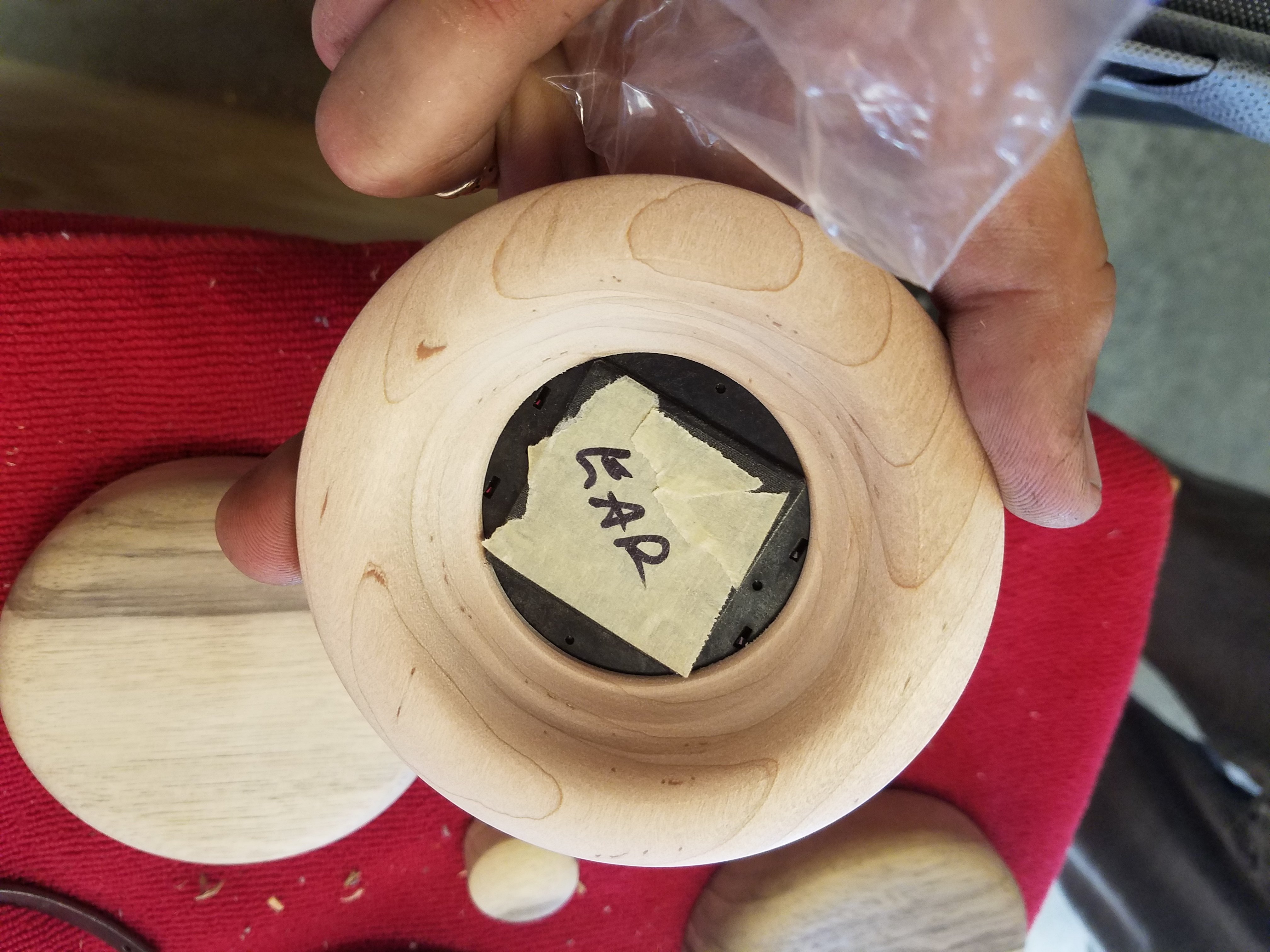
Above: Panasonic WM-61A electret microphone capsule, Rubber Shock Absorber from T50RP, Panasonic WM-61A JFET, and T50RP baffle screw.
You can see why you must be fast when soldering such a tiny component. Get in and get out quickly with a 1 to 2 second application of your iron to the solder terminals. The "reflow" technique described by Conover works and it's easy, even for beginner like me. If, however, you do not succeed reflowing the terminal solder after 2 seconds, let the mic capsule cool completely before making another attempt. Otherwise, you may destroy the tiny JFET inside the mic.
Here, I have a mic secured and ready for reflow soldering. I have stripped 1/32" of insulation and tinned the exposed wire. Dab a tiny bit of flux on the solder pad and wire tip using a toothpick.
Hemastats hold the pre-tinned wire with the tip perpendicular and centered on the top of the terminal solder pad. A gauze cushion prevents the hemastats from damaging the wire. Use 26 gauge wire, or smaller.
The hemastats are elevated and taped in place so the tip of the wire is in the proper position and won't move when you touch the terminal solder pad with the pre-tinned tip of your iron. I set mine at 500 degrees F. As Conover describes, touching the solder pad for 1.5 seconds melts the solder causing it to "reflow." Surface tension will self-center the tip of the wire as it drops 1/64" into the molten solder. Do the other side the same way, test for continuity, and apply a dab of epoxy to seal and secure the wires so they won't pull loose during use.
Here are the WM-61A microphone installed in a 1/8" TRS stereo plug and my artificial ear canal following John Conover's design. This mic plug was made by kibblefat using the Linkwitz mod. Here's the link to the Linkwitz mod:
http://www.linkwitzlab.com/sys_test.htm#Mic
Look for the "Microphone" tab for a description of the Linkwitz modification of the Panasonic WM-61A.
IEM measurement kit. Masking tape was applied to seal the mic to the artificial ear canal.
IEM measurement kit: My Phantom Power Supply following wdahm519's design has not yet been "boxed." kibblefat's IEM microphone assembly is plugged into the Phantom Power Supply Mic IN jack. My Shure SE 535 IEM is sealed inside the artificial ear canal opening. A 1/8" TRS stereo cable is plugged into the Phantom Power Supply Mic OUT jack and the other end goes to my MacBook Pro LINE IN jack. My soundcard headphone OUT is connected to my Dacmini via a glass optical interconnect. REW software collects, analyzes, and graphs the measurement data.
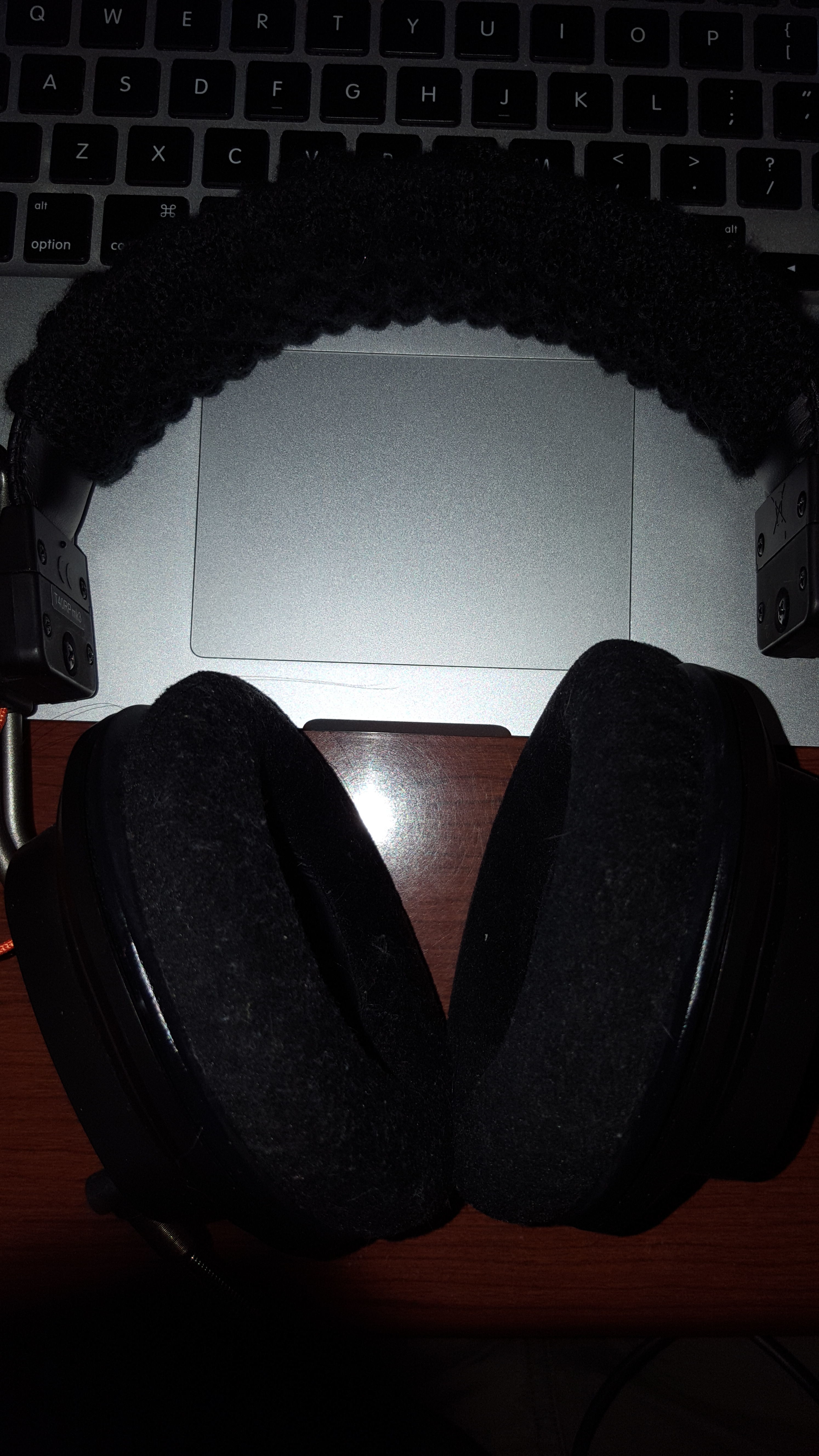
I performed a "left parietal-occipital craniotomy" on my styrofoam dummy head so I could insert an artificial ear canal. Removing this section of the skull also allows access for coupling my calibrated Galaxy CM-140 SPL meter to the dummy head. This was necessary in order to position the SPL meter out of the way of headphone placement onto the dummy head.
Felt around the ear serves as "hair replacement." I have not been able to make consistent measurements with the dummy head system compared to "in my ear" measurements. I found it difficult to get a good seal of ear pads to the dummy head. Headphone placement was difficult to determine and standardize because of the lack of tactile and proprioceptive feedback provided when I measure with the mic in my ear. I have found that making measurements in my ear, instead of the using the dummy head, are more consistent because I can feel where the headphones should be placed based on comfort and the position I typically wear headphones. In-my-ear measurements also insure I have a good seal, or not, based on "the feel" of the headphones on my head.
In-my-ear mic placement is fairly easy to standardize based upon the same tactile sensory information. I can closely match the mic position and depth in my ear canal from one measuring session to the next. There are slight discrepancies but I believe they are inconsequential. Of course, this is not an issue when making a series of measurements within a single measuring session as long as you don't remove the mic.
Edit: Note that the wired mic is installed, with the mic facing outward, in an IEM foam ear tip, triple flange, or similar. This allows a tight seal to protect your hearing from the tone sweep that can be loud. Also, this allows for better consistency of mic placement and depth in your ear canal.
Here's one used by micmacmo:
and here's one I use mounted in an Etymotic foam ear tip:
re: your measurment of shure 535 vs tyll's - noticed that your artificial canal implementation differs from conover's which recommends pushing both iem and mic capsule flush against the inner tubing. substantial gap in your implementation may be leading to the different measurements.
re: your measurment of shure 535 vs tyll's - noticed that your artificial canal implementation differs from conover's which recommends pushing both iem and mic capsule flush against the inner tubing. substantial gap in your implementation may be leading to the different measurements.
Good call. I missed that detail and cut the 2.5 inch length for the larger tube. Scrolling down a fit further, Conover used a mic mounted to a metal extension that he placed flush with the other end of the smaller interior tube. I'll cut my longer tube down to size so my plug mic will sit flush with the other end of the smaller tube. Results to follow.
I documented the mods I made to my T50RPs in preparation for a dual-entry recable. The document (a google photo album) doesn't cover how to make a cable nor does it provide a step-by-step guide. It illustrates the modifications I made to the cups and what I would do differently next time. https://picasaweb.google.com/109082108141353641215/FostexT50RPRecable
I don't claim to offer anything original here; I borrowed shamelessly from wje and dogwan.
Results:
I did it to simplify modding. Because of the presence of the jack in the left cup, the cups weren't identical and the left cup invariably had more air leakage than the right cup. This meant that all mods had to account for the difference. This way, I have to deal with this problem less, although subtle imbalances still occur.
If there were acoustic benefits, they were minor compared to those of most of the mods we discuss in this forum.
I have the stock cable housing and I have never heard any channel differences at all. Only thing I'm careful of is to use the same amount of damping materials in each cup despite the slightly smaller space to work with in the left cup.
This site uses cookies to help personalise content, tailor your experience and to keep you logged in if you register.
By continuing to use this site, you are consenting to our use of cookies.


")
