


hakuzen
Headphoneus Supremus
- Joined
- Feb 9, 2016
- Posts
- 1,806
- Likes
- 2,682
Links to sections:
- cables below 400mΩ measurements
..............pics, comments, and links, part 1
..............pics, comments, and links, part 2
..............pics, comments, and links, part 3
..............pics, comments, and links, part 4
..............pics, comments, and links, part 5
..............pics, comments, and links, part 6
- cables for KZs (below $40, most below $25) measurements
..............pics, comments, and links, part 1
..............pics, comments, and links, part 2
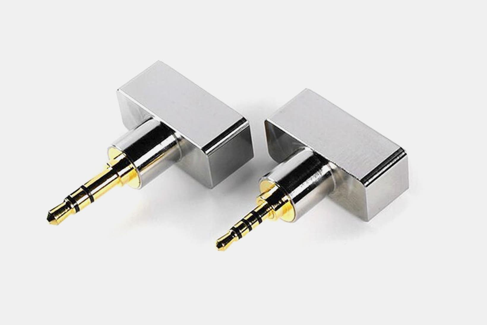
- jack adapters (measurements, pics, and links)
I've created this thread because some people suggested that the measurements info should be found easier, rather than buried in posts from different threads, and because updating the info is also easier for me this way.
We can keep discussing in the low end cables thread, or KZ thread in case of cables for KZs.
But feel free to comment or discuss here as well, if you like..
Rules are the usual head-fi rules for threads.
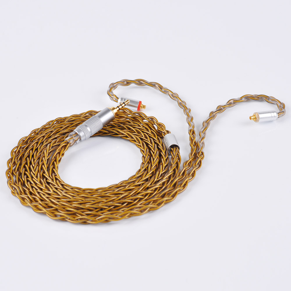
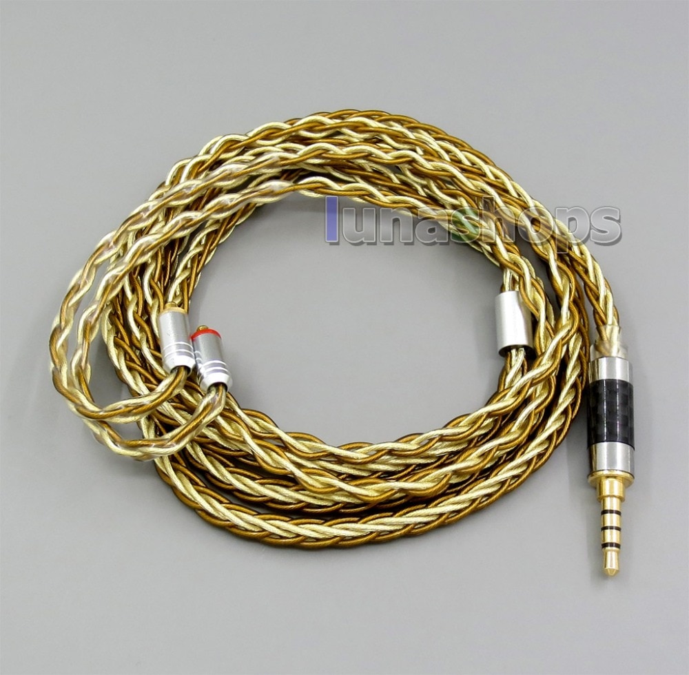
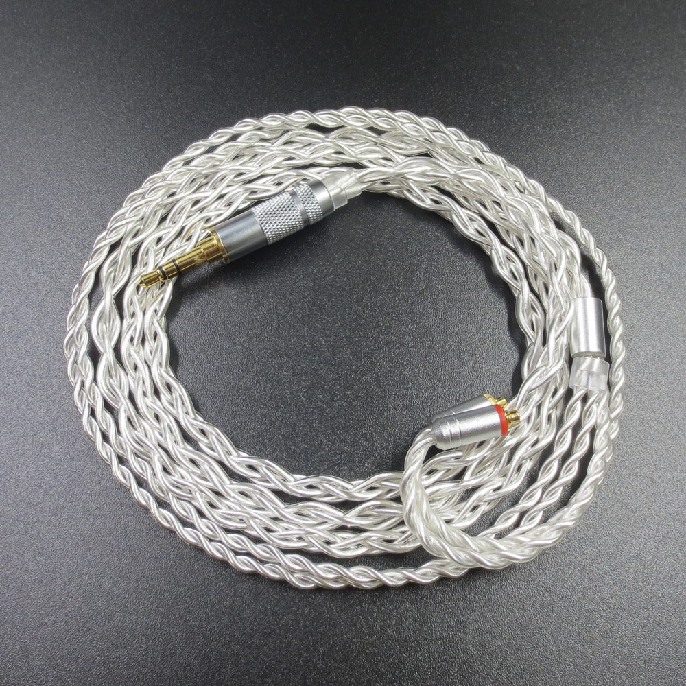
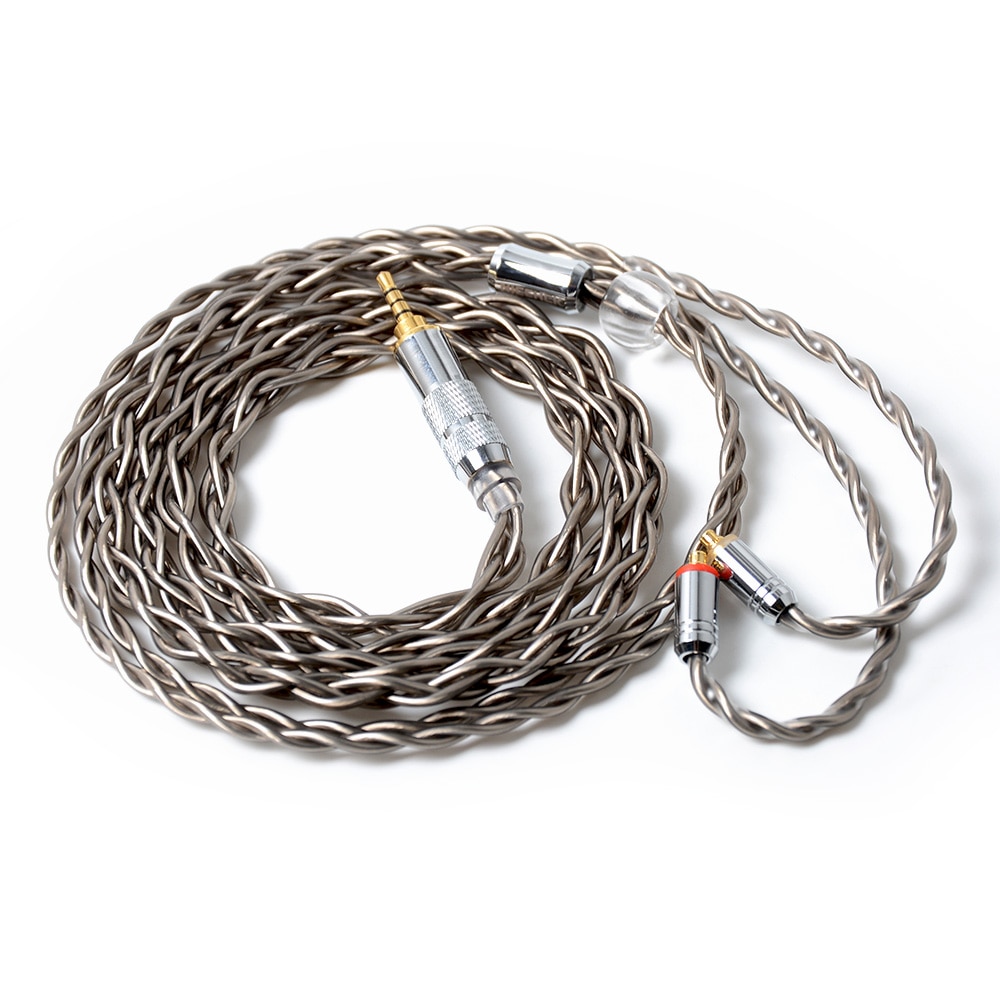
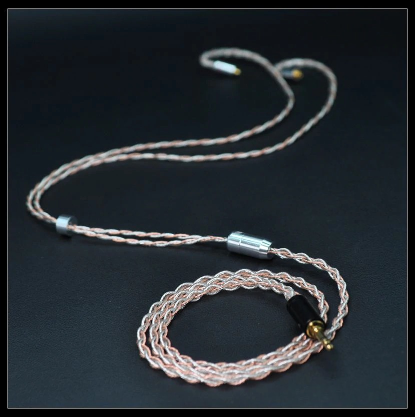
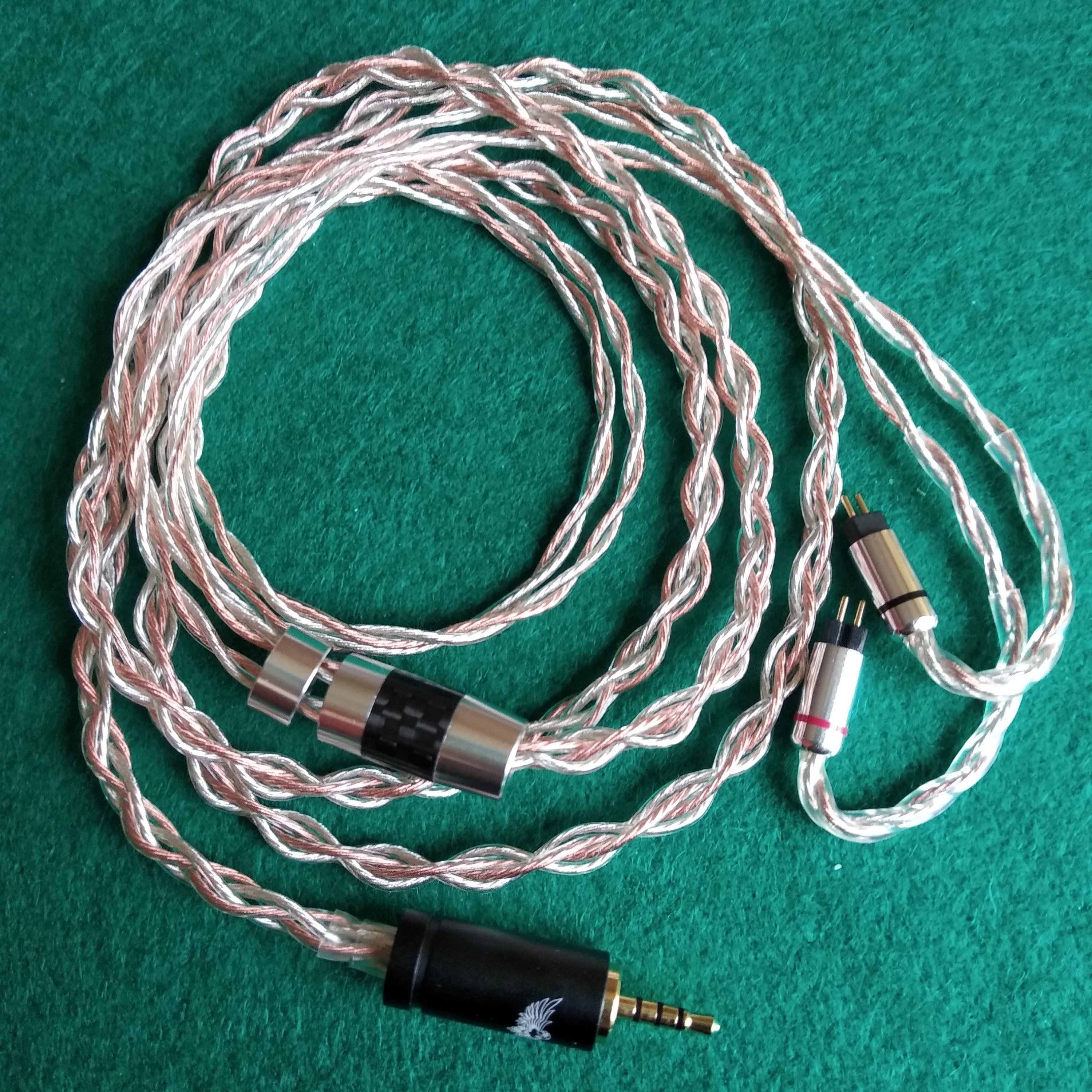
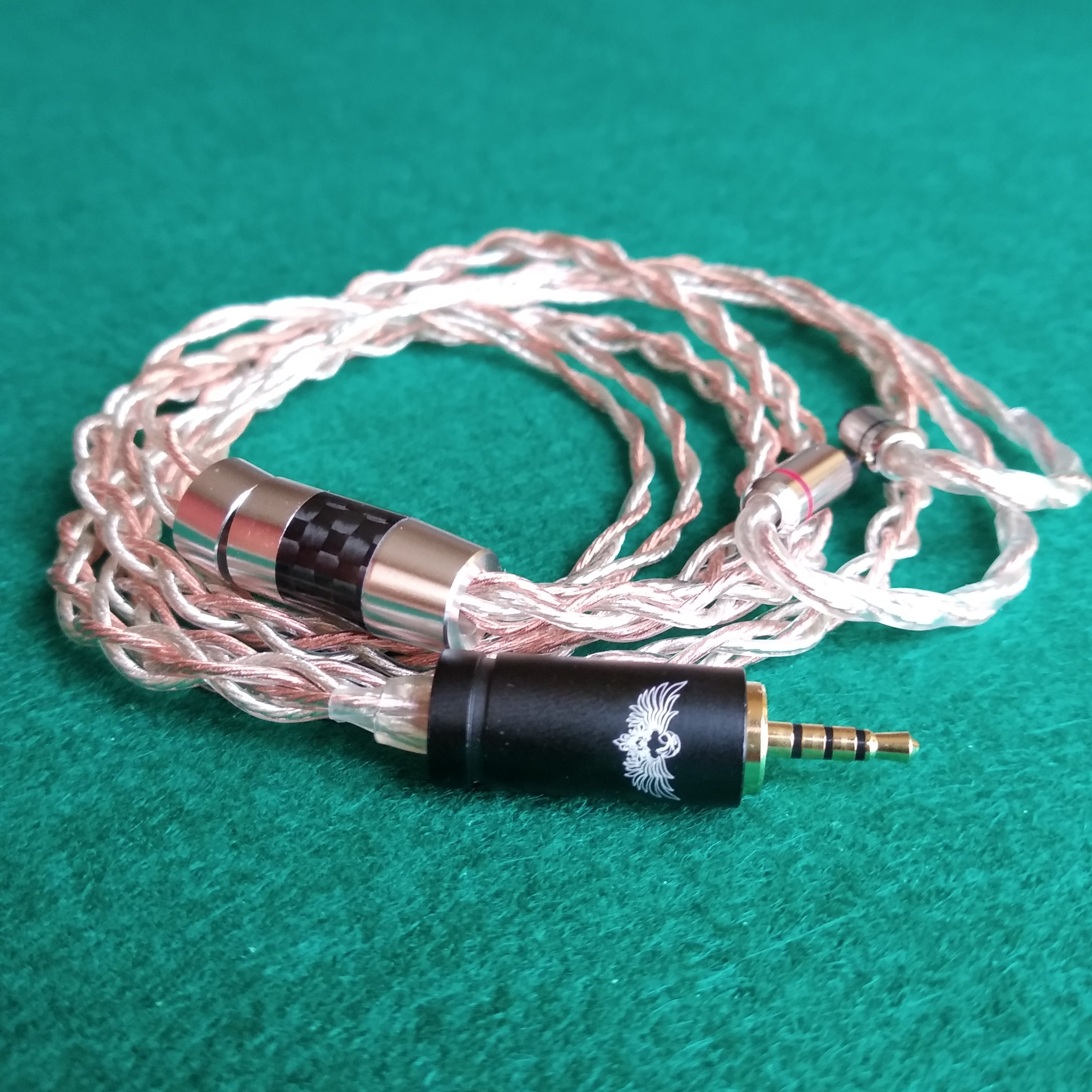
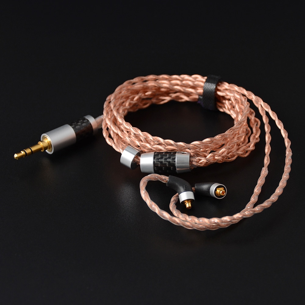
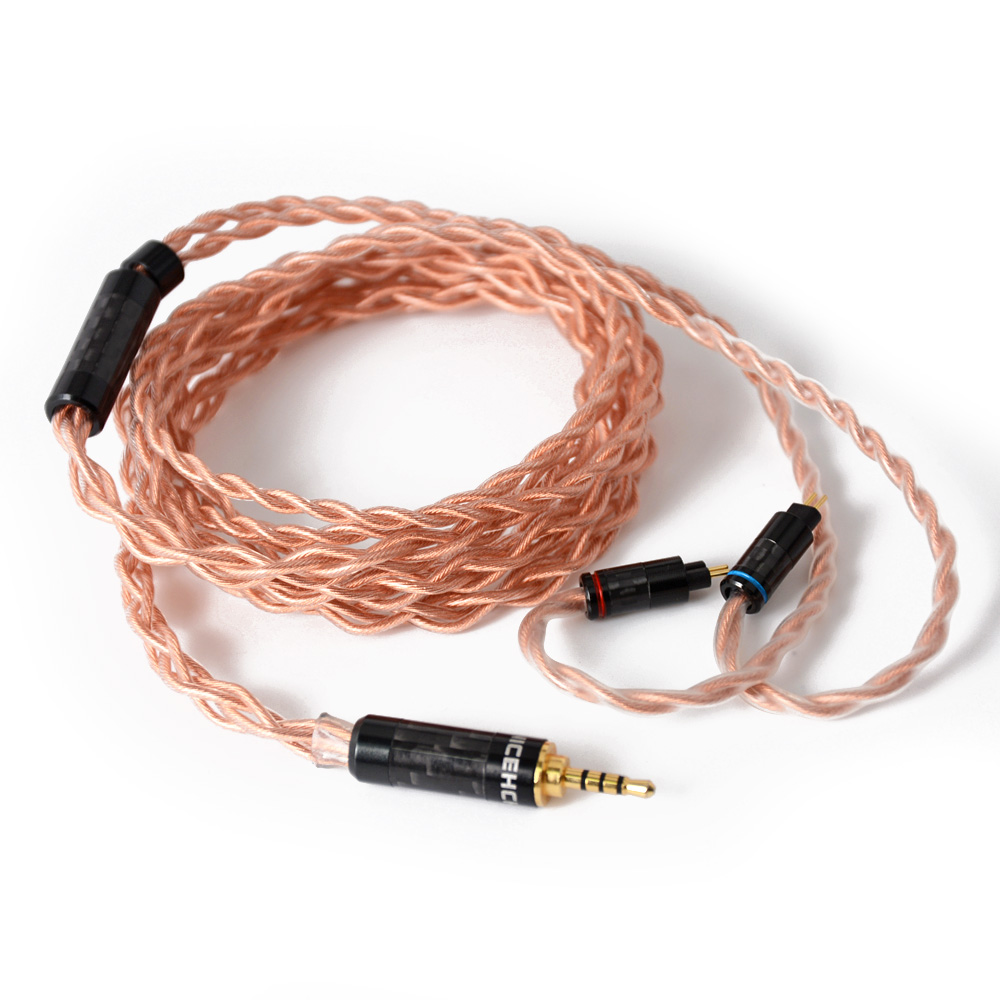
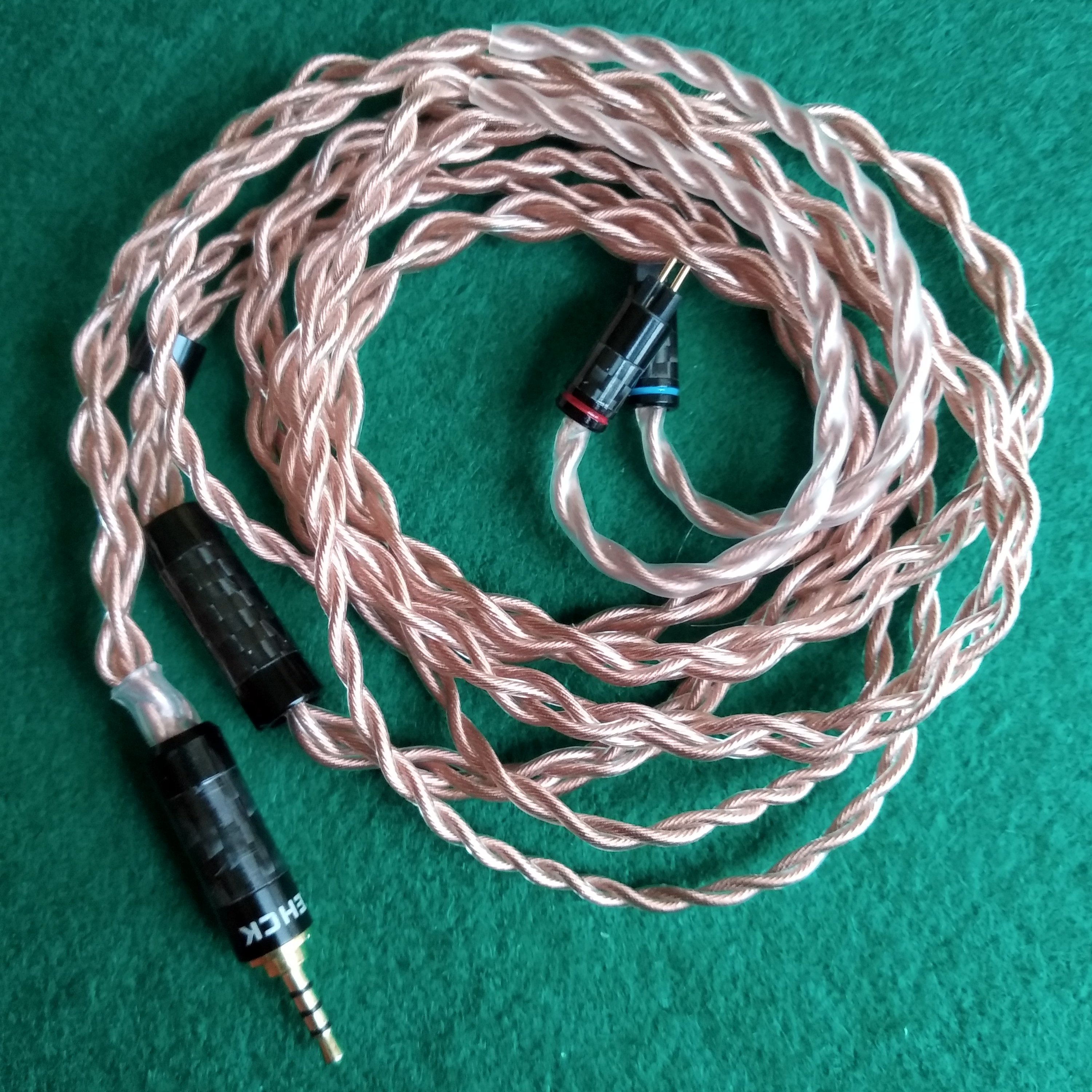
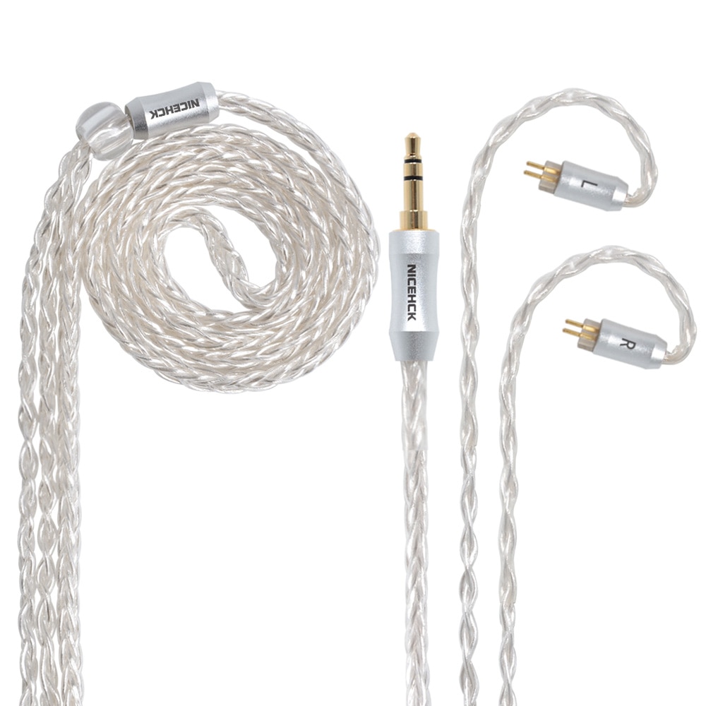
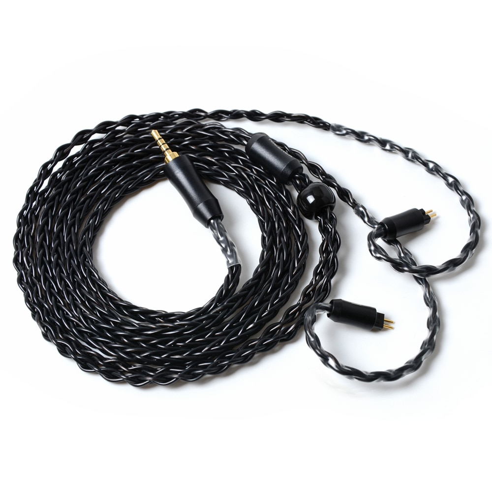
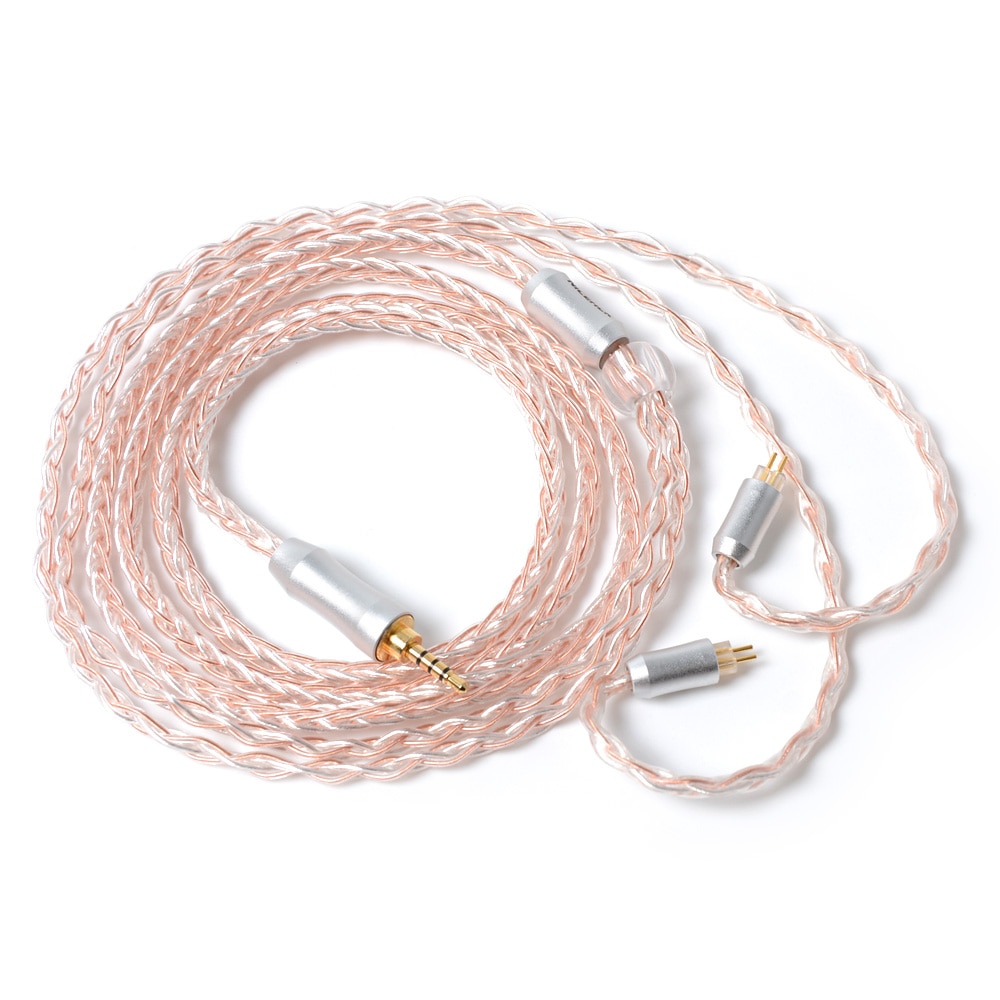
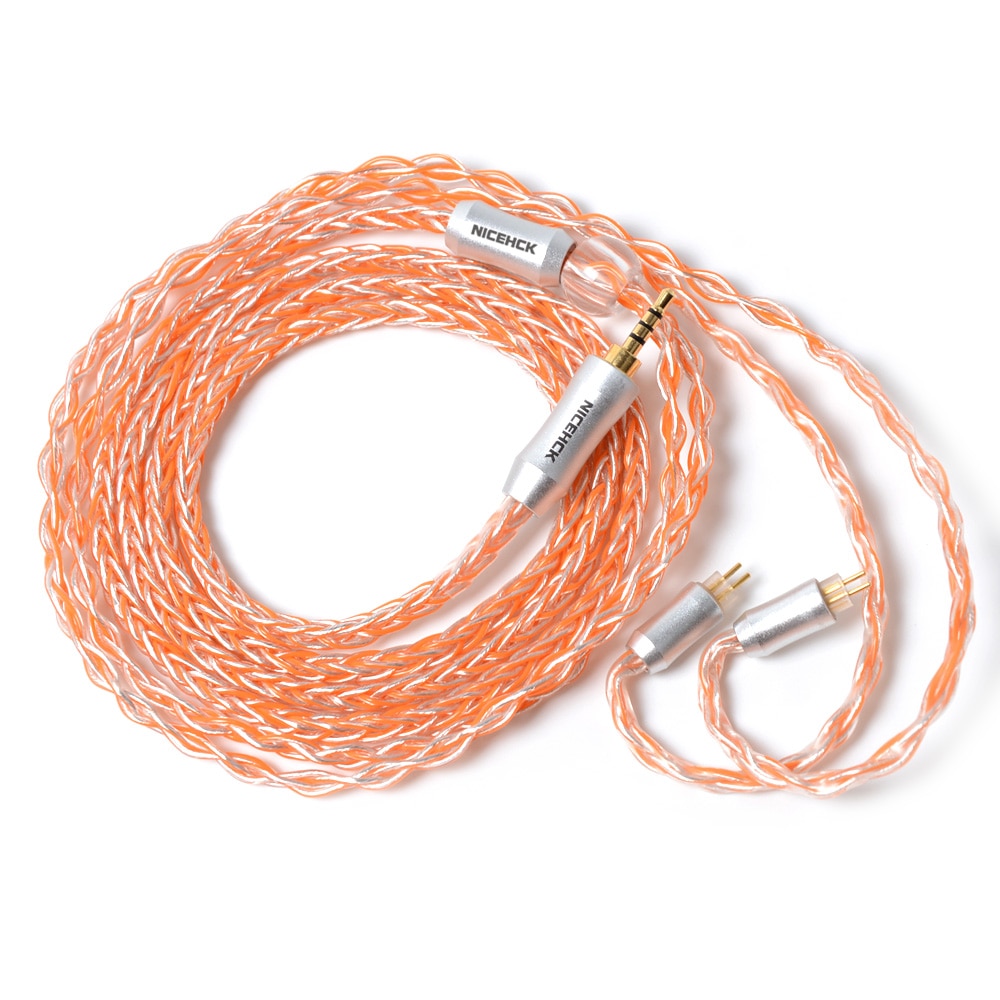
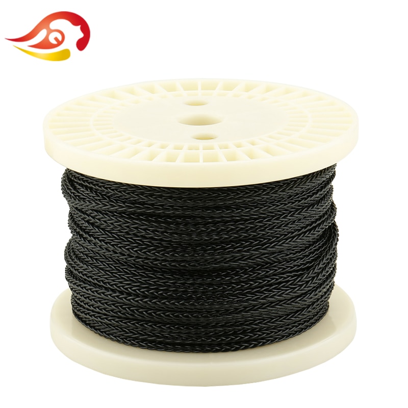
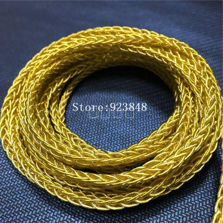
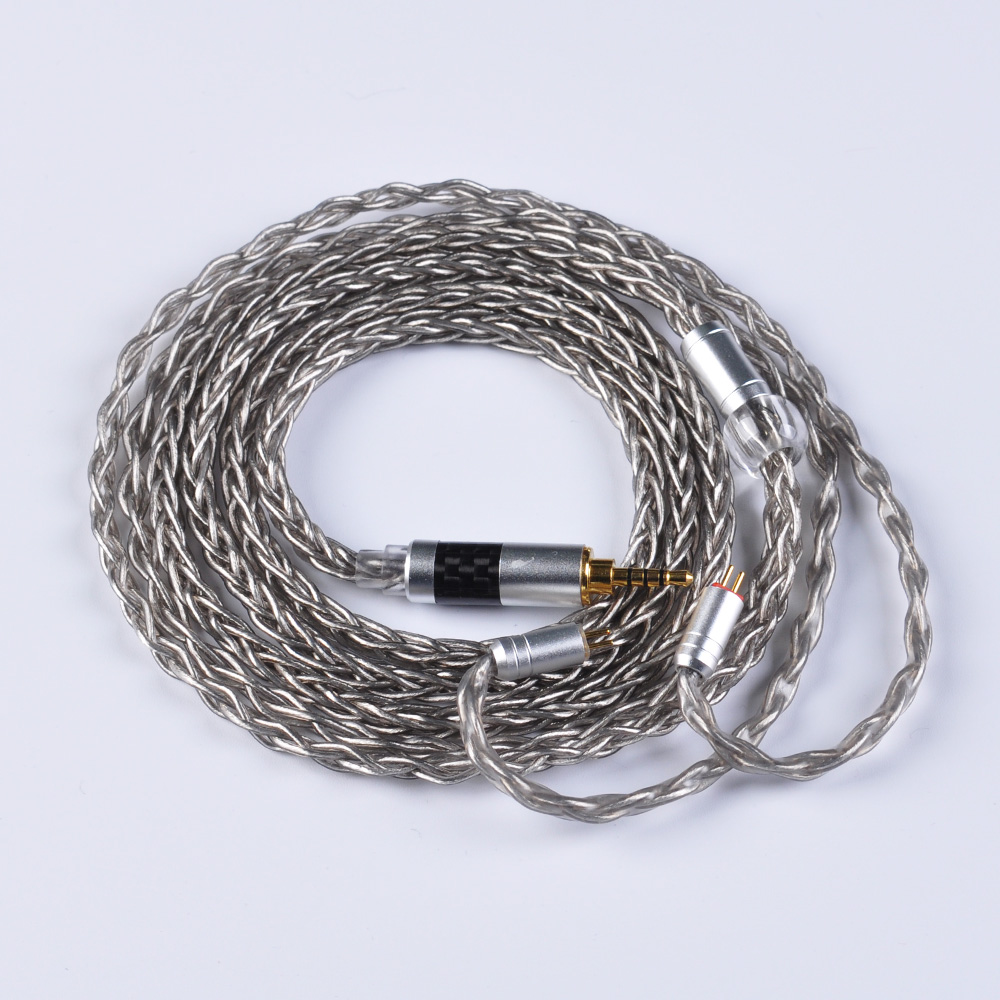
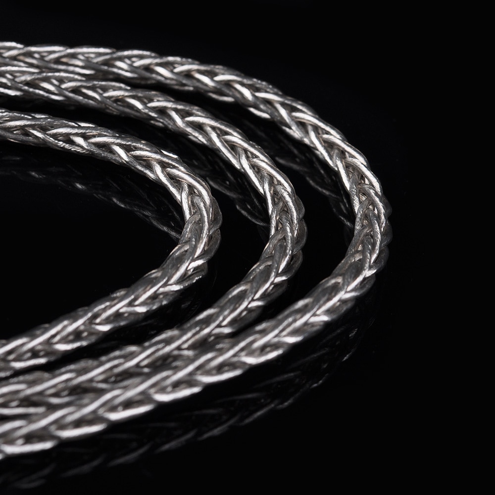
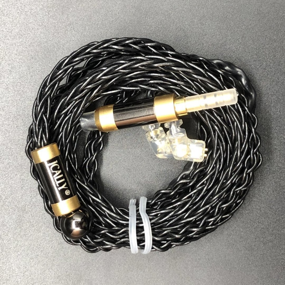
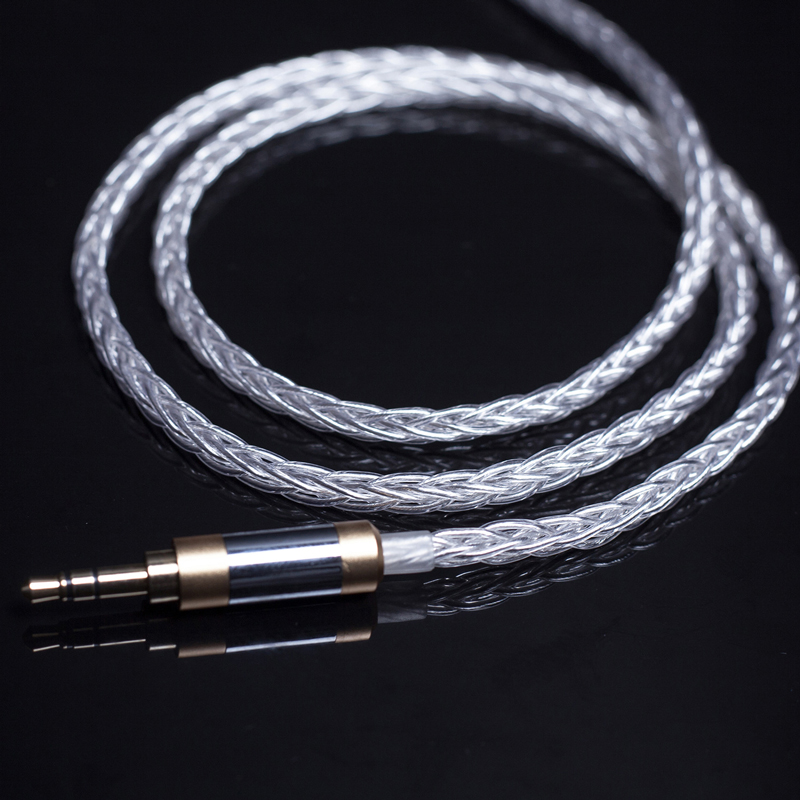
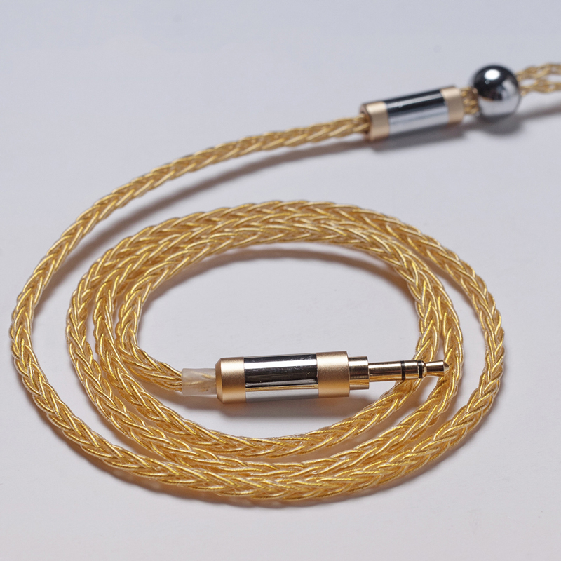
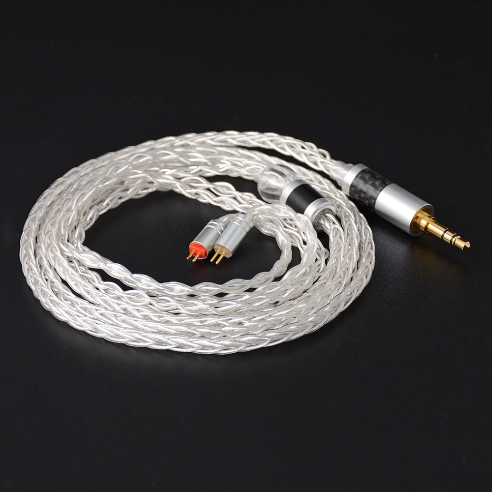
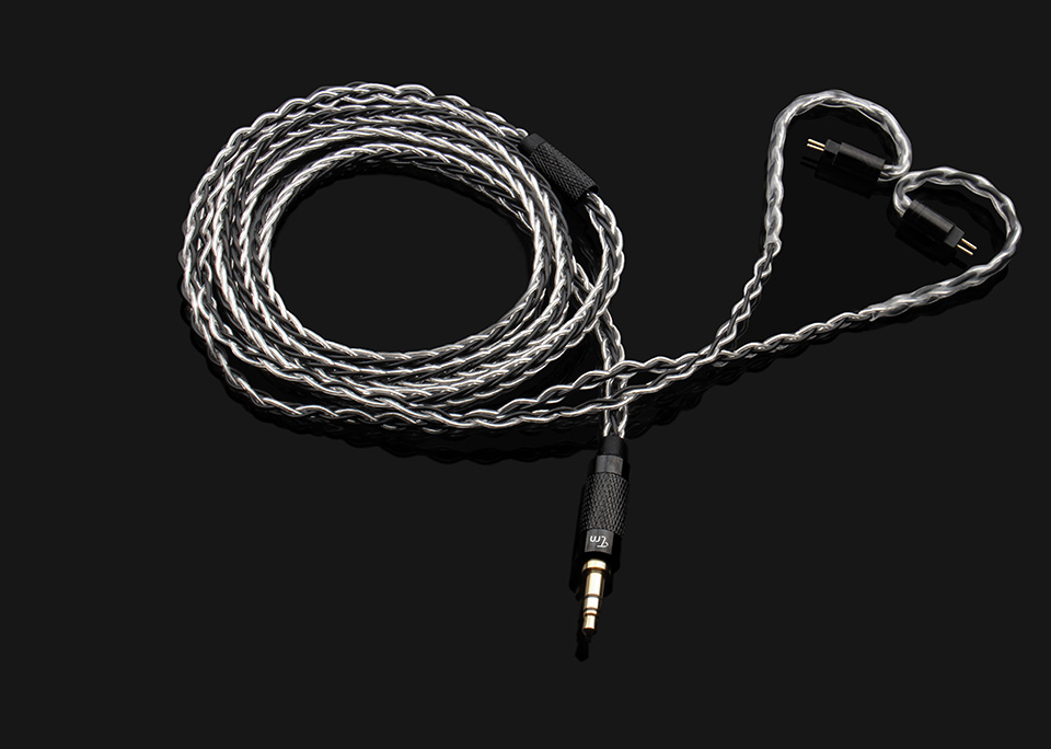
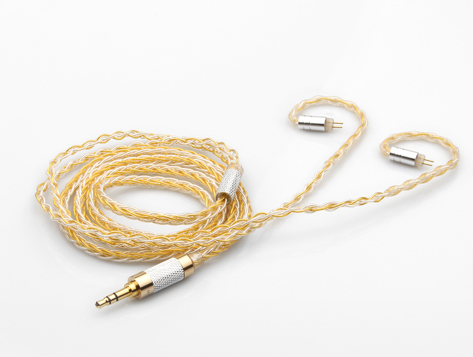
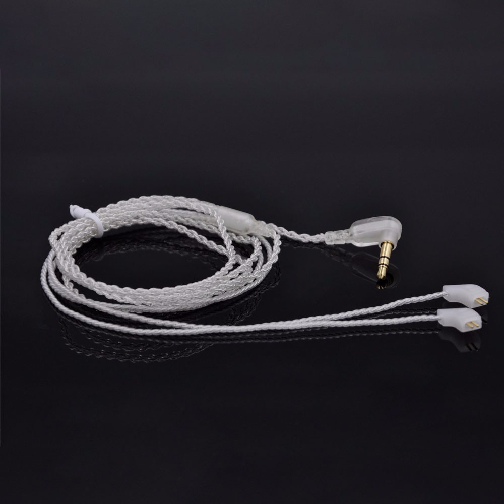
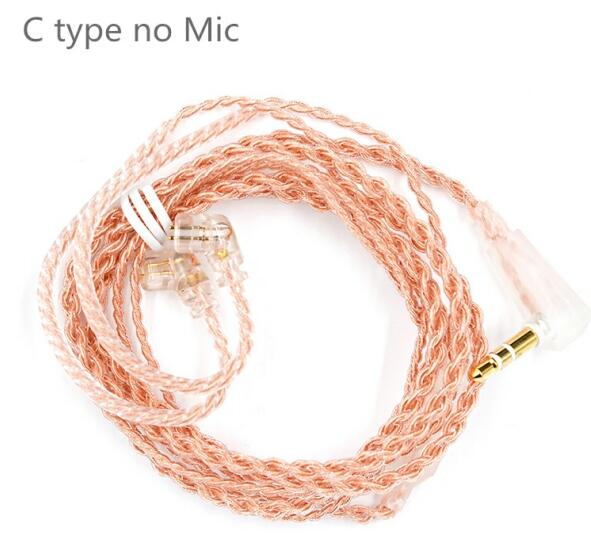
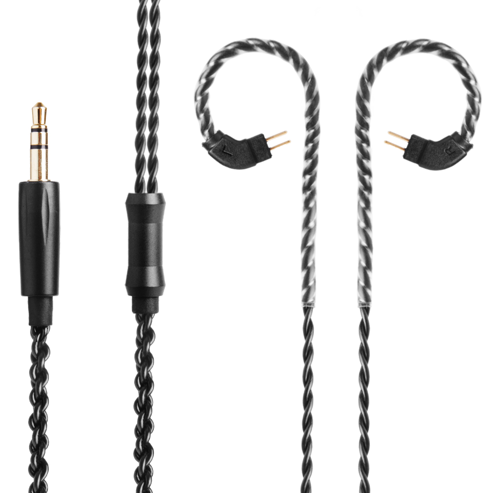
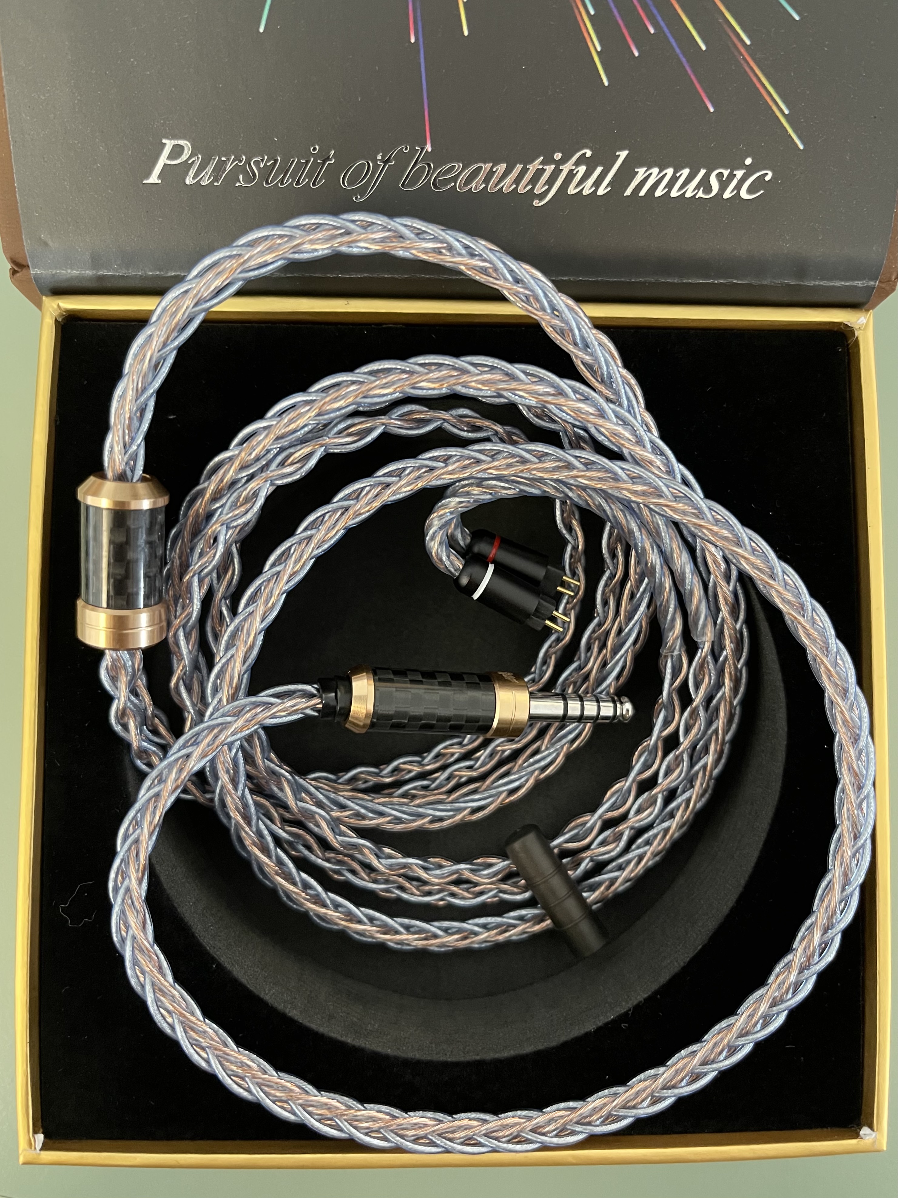
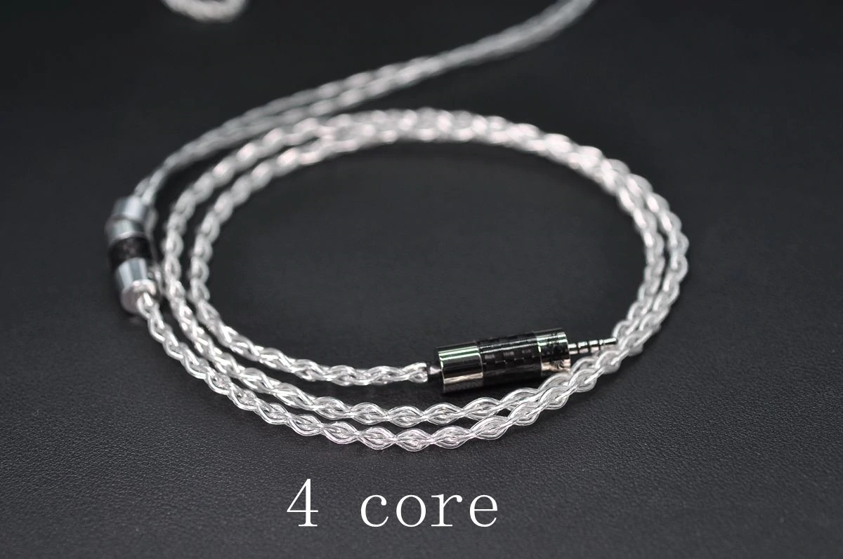
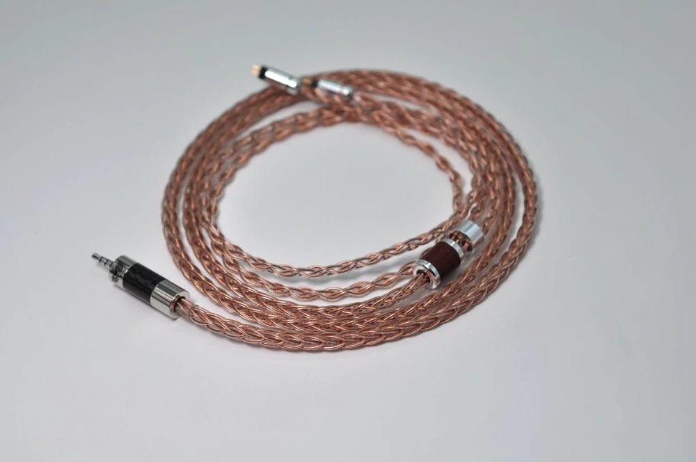
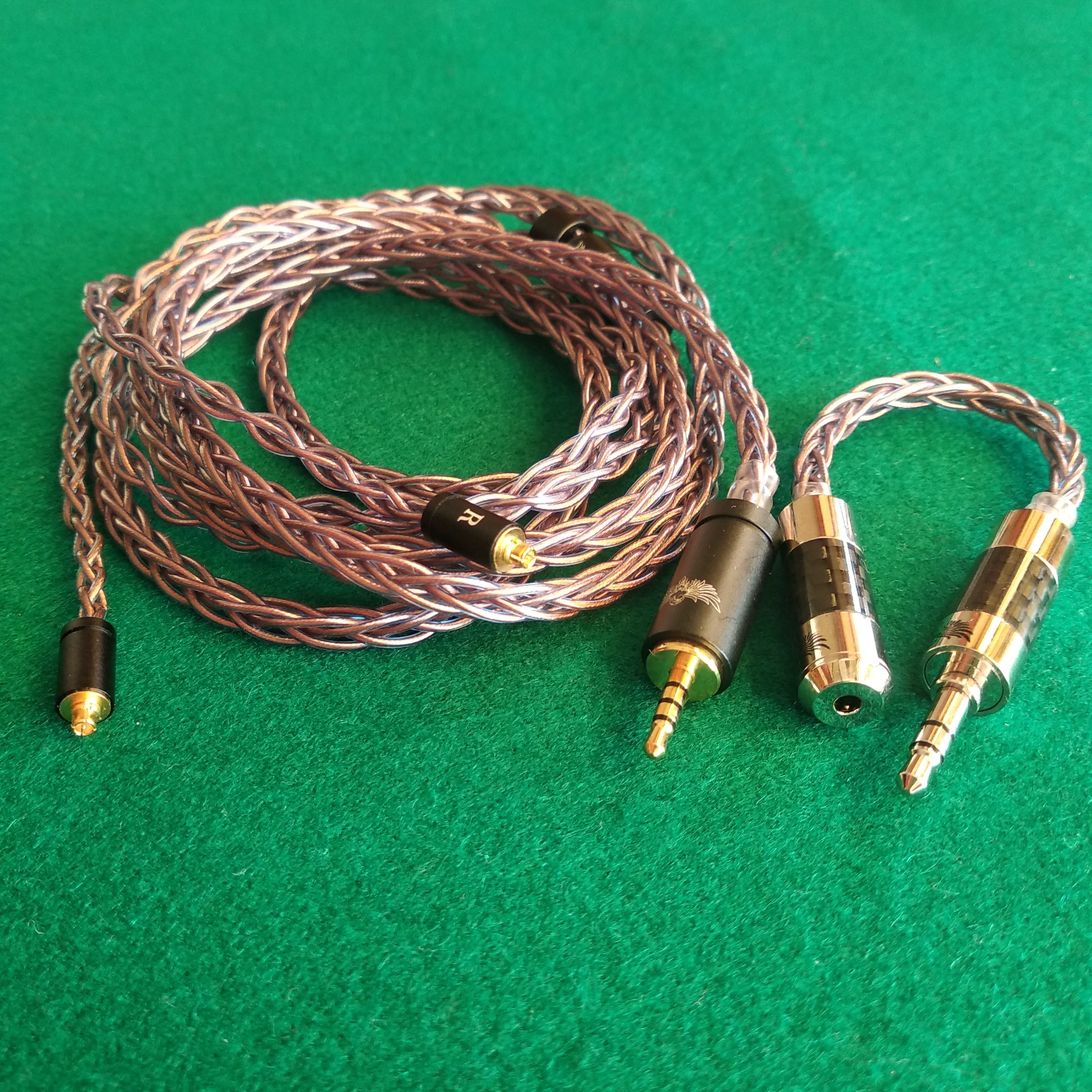
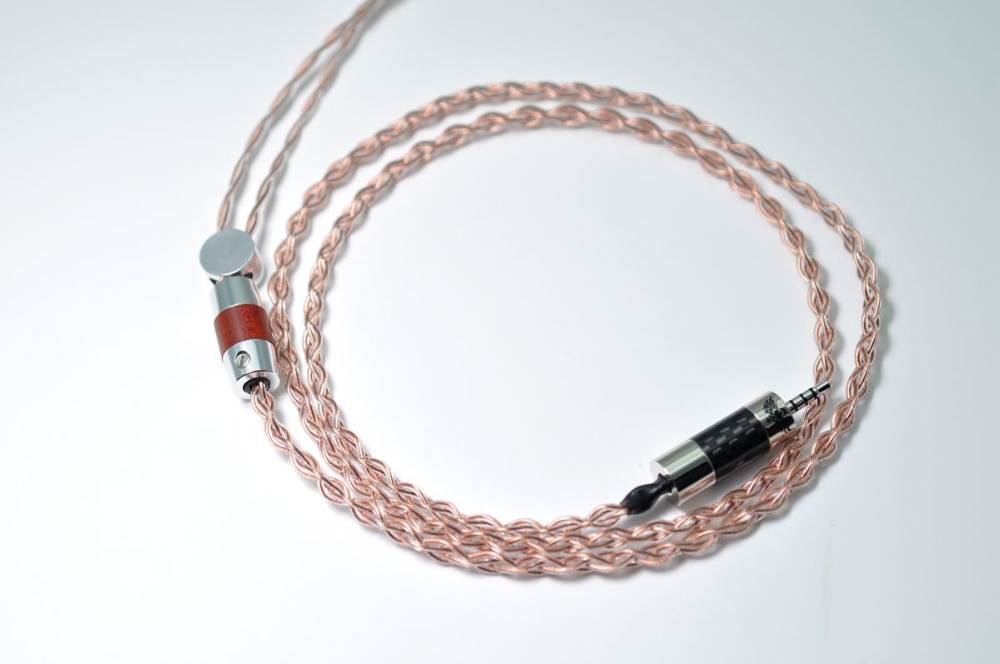
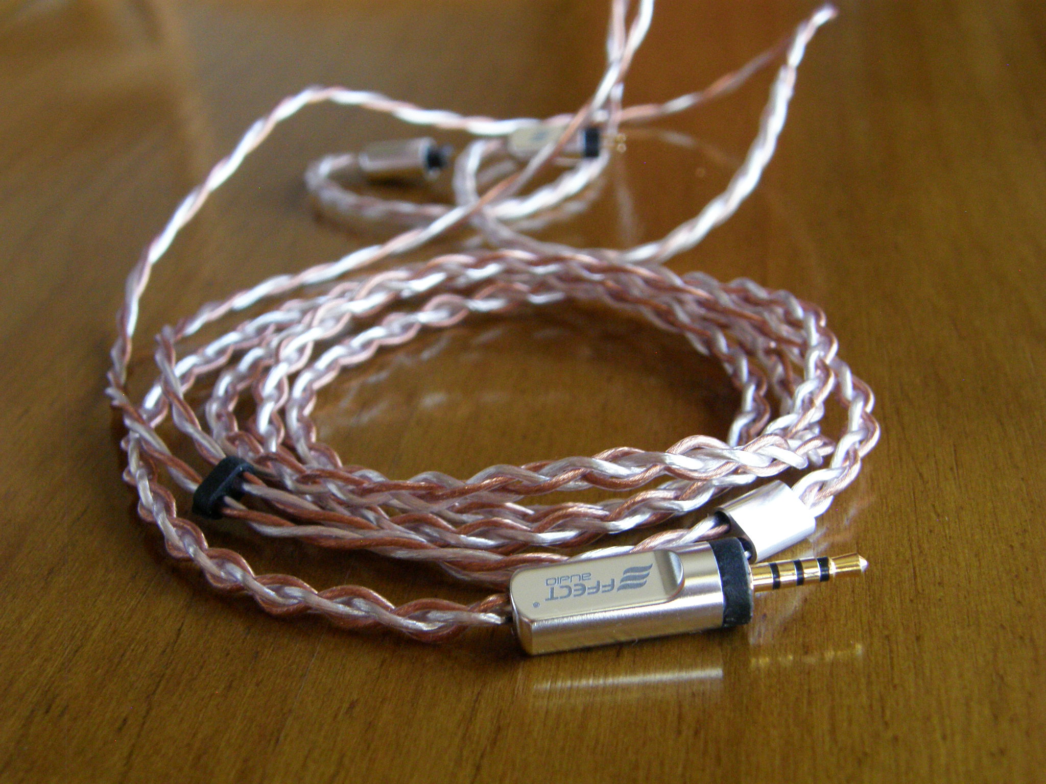
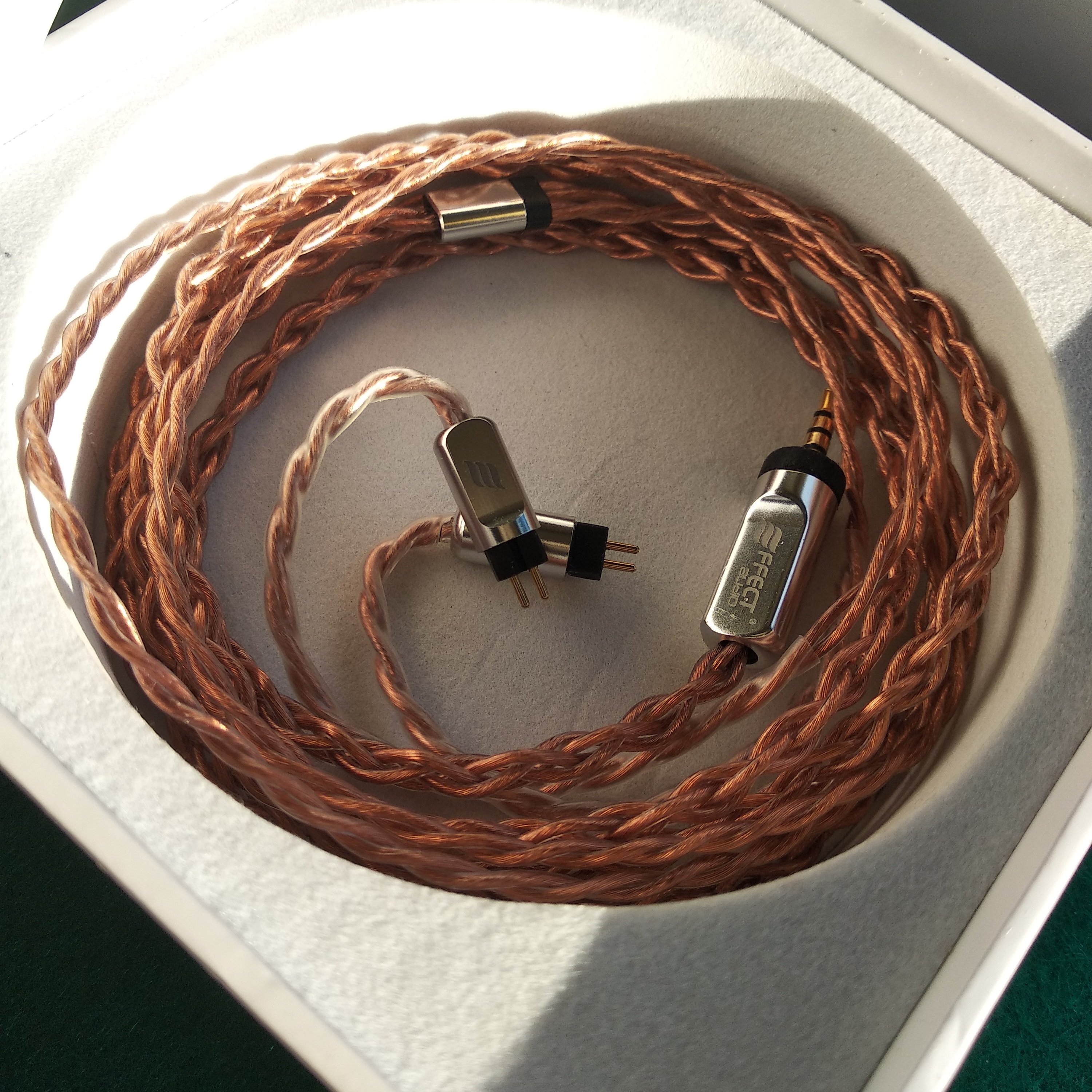
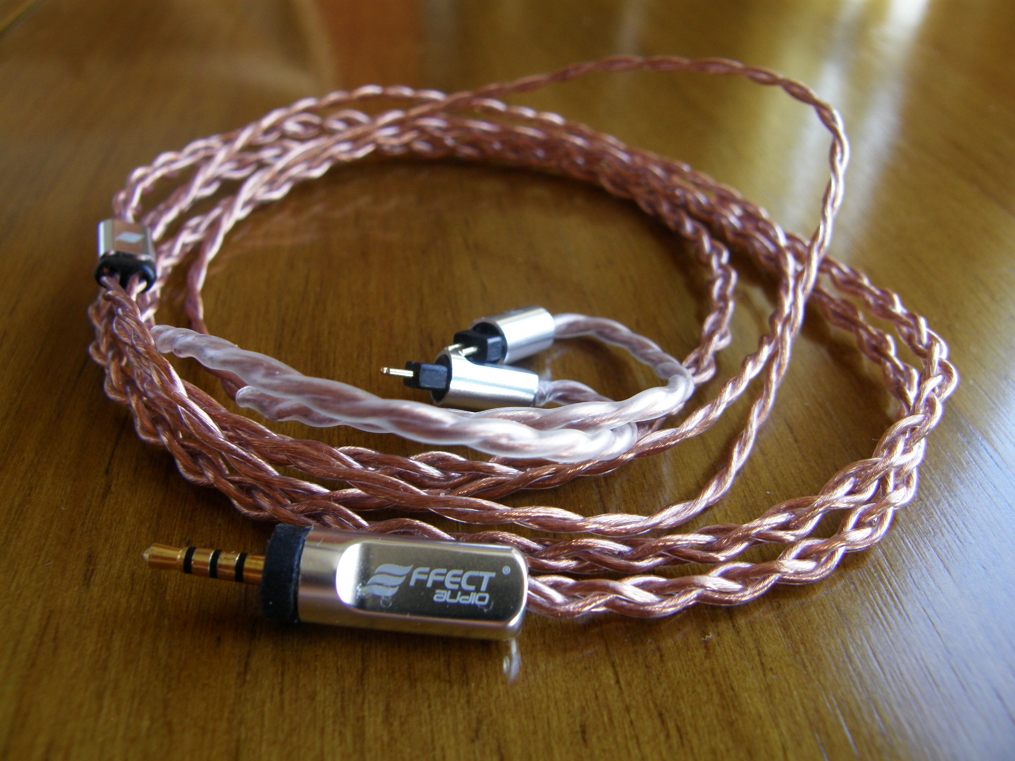
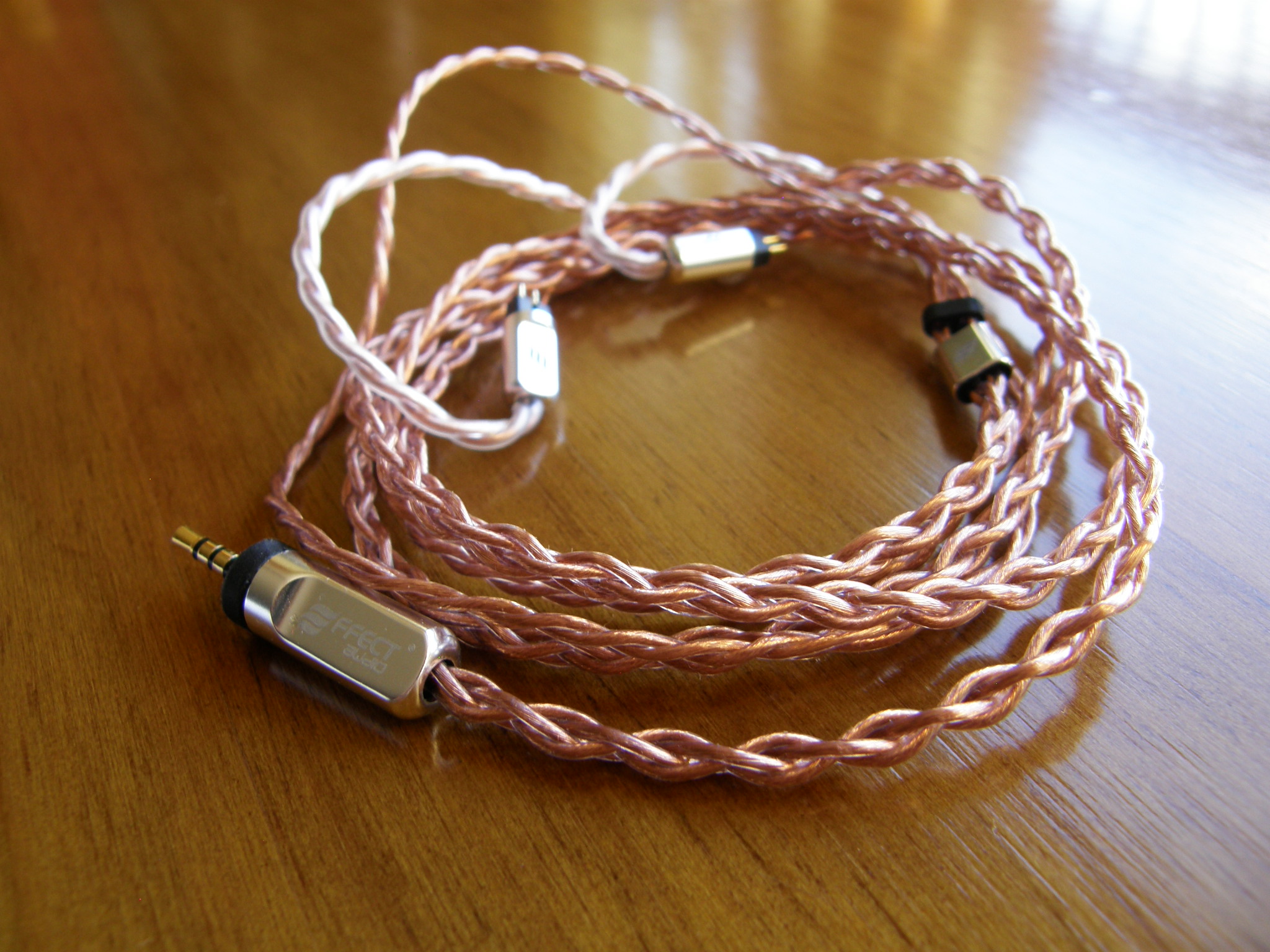
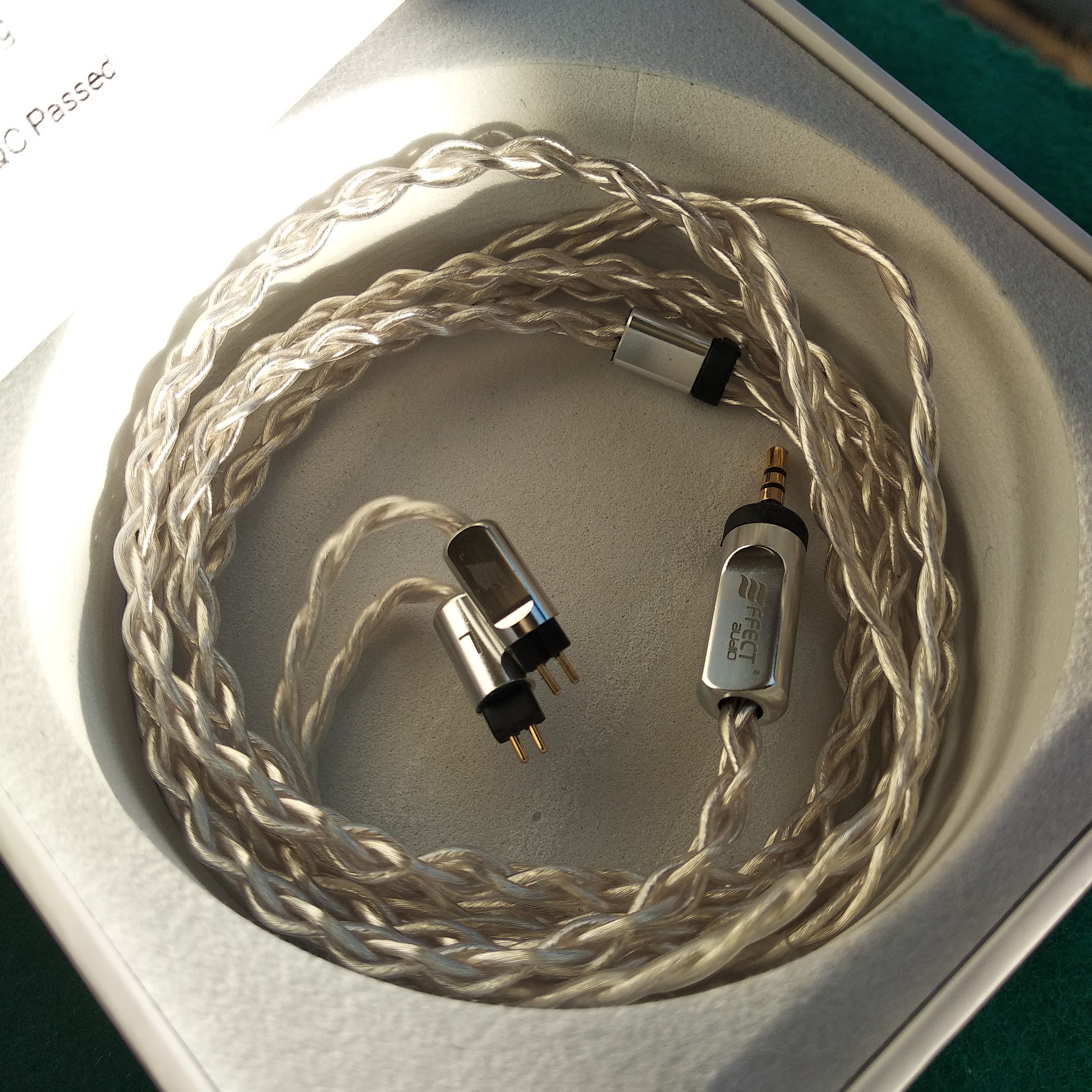
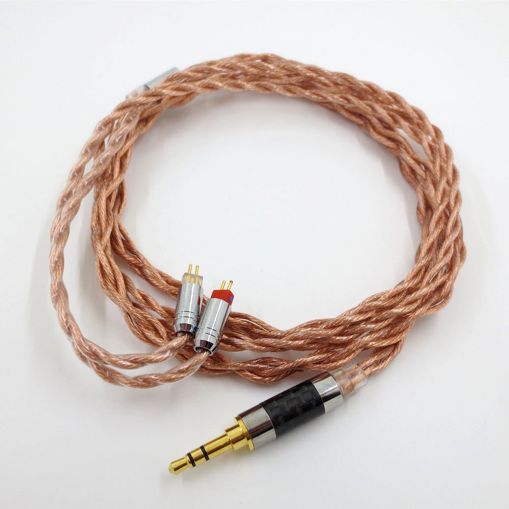
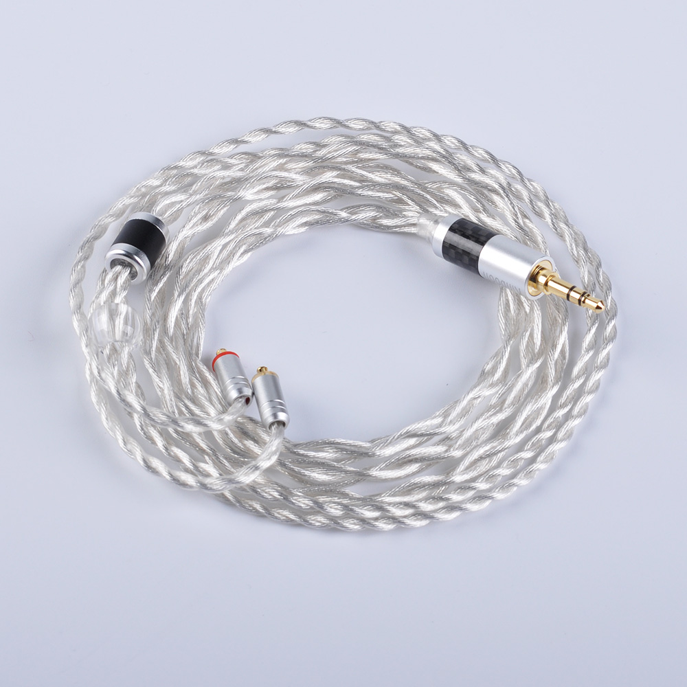
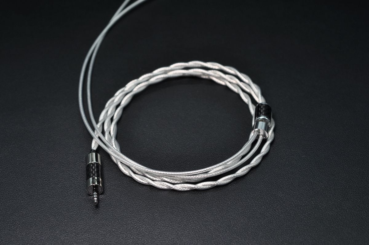
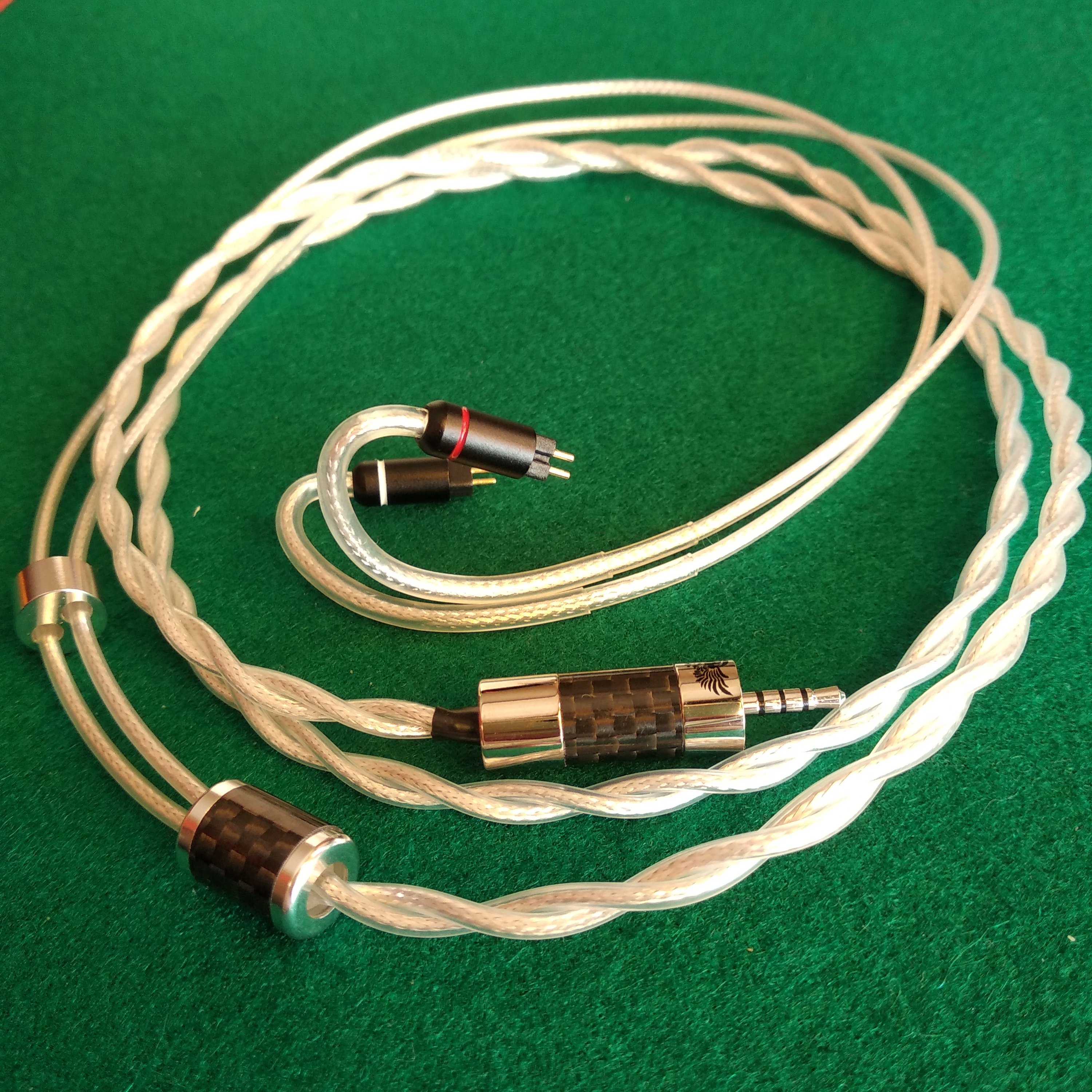
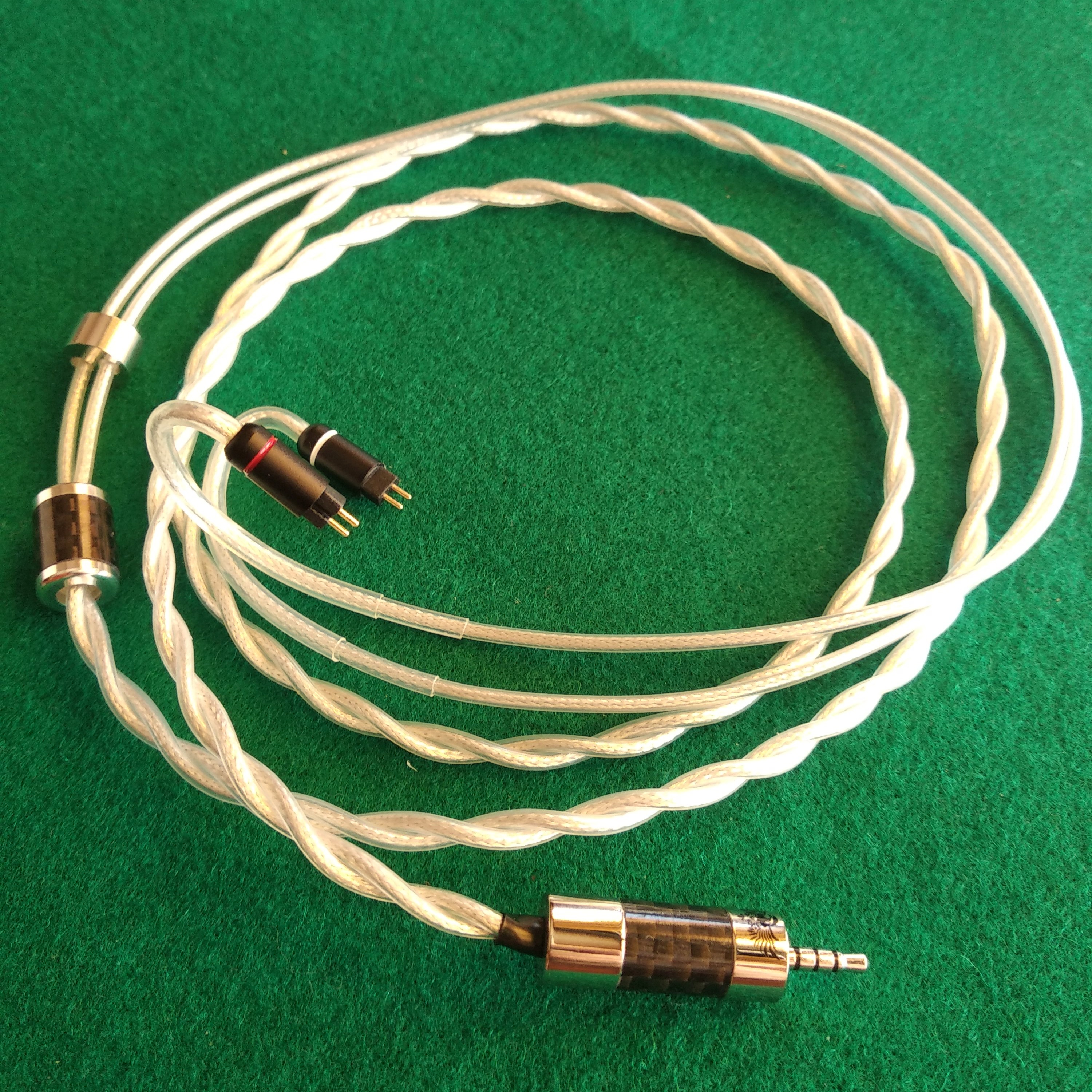
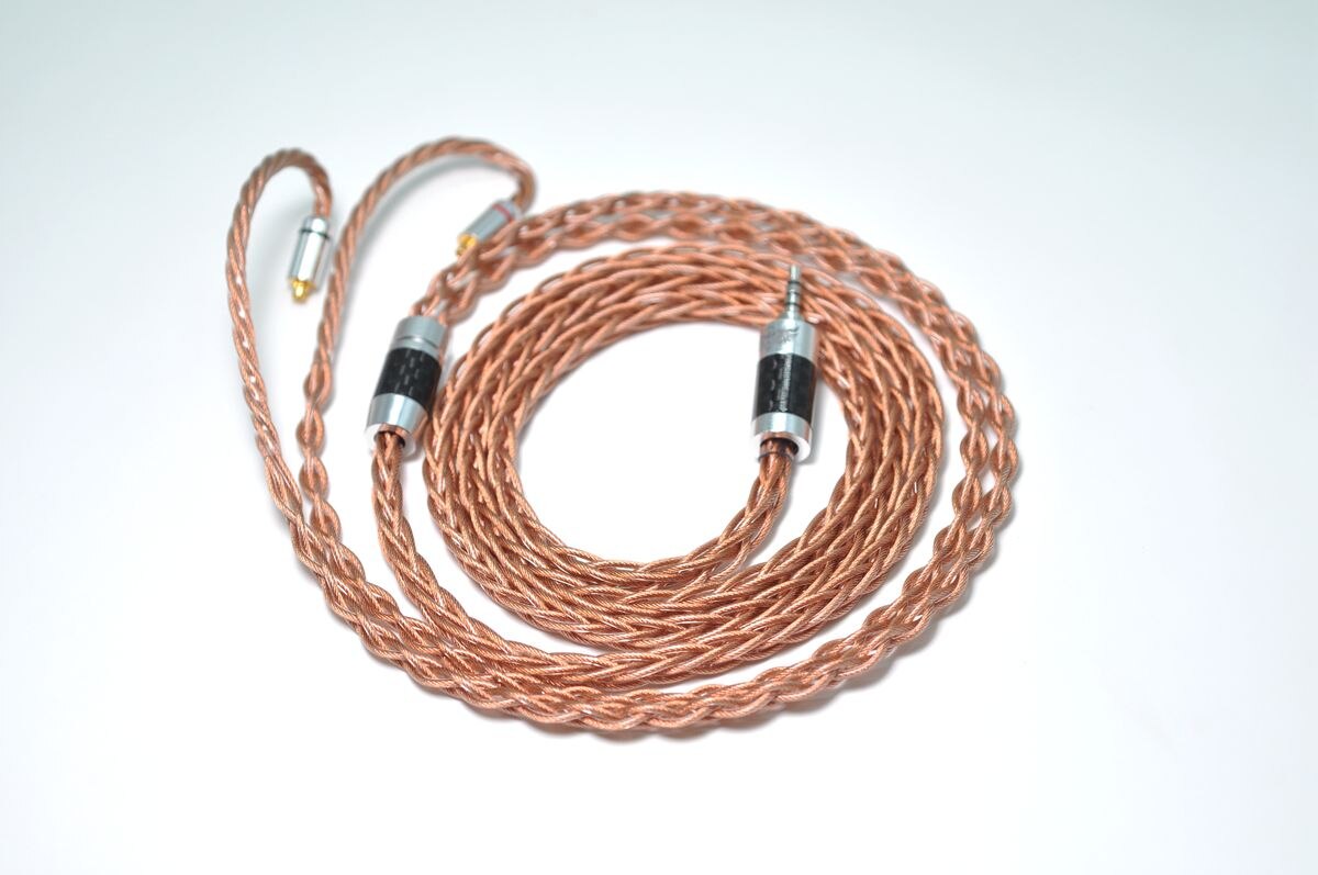
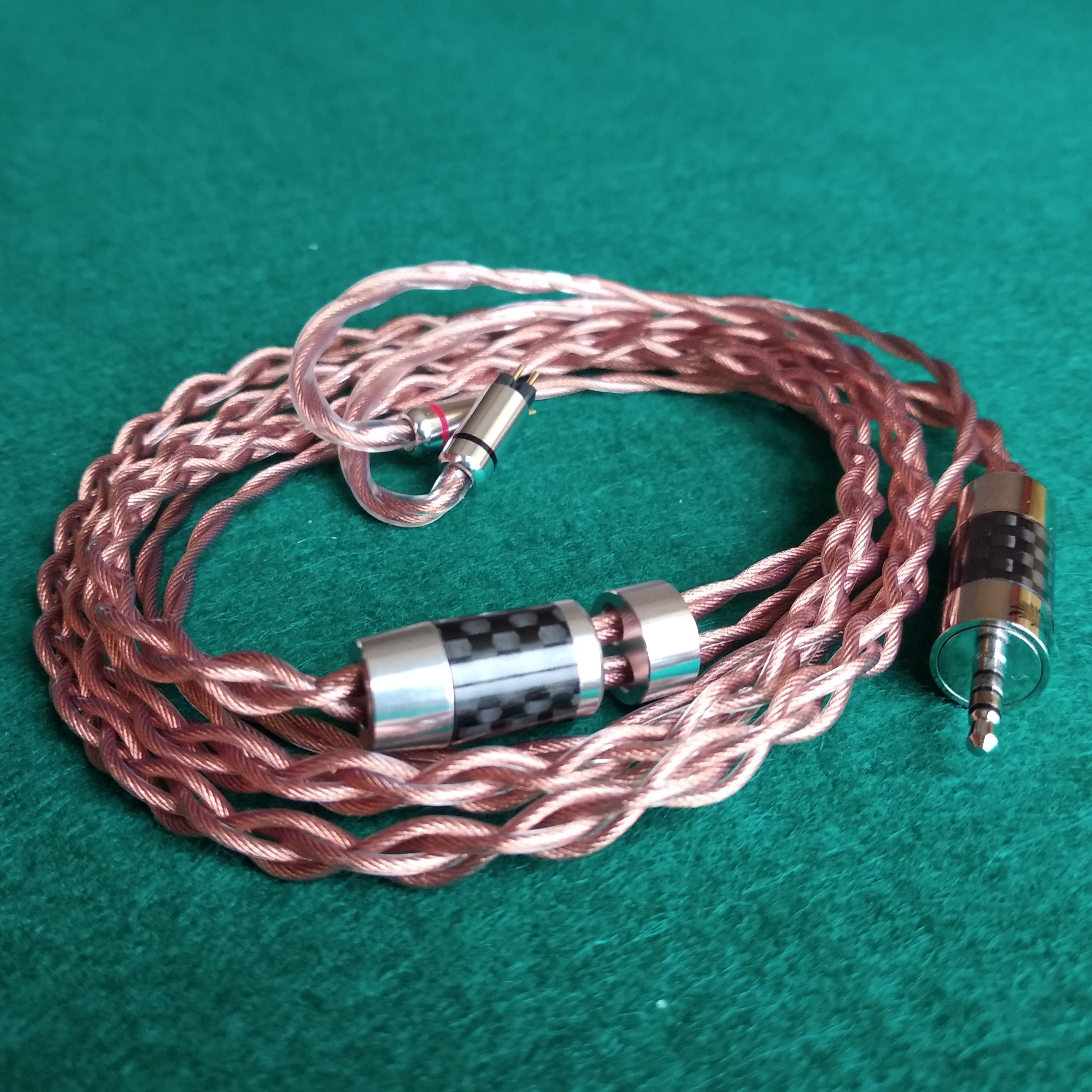
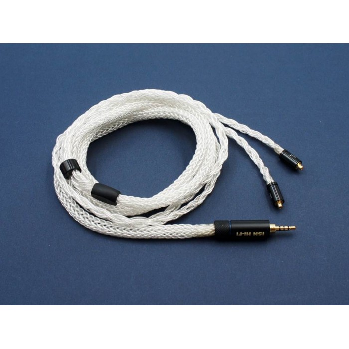
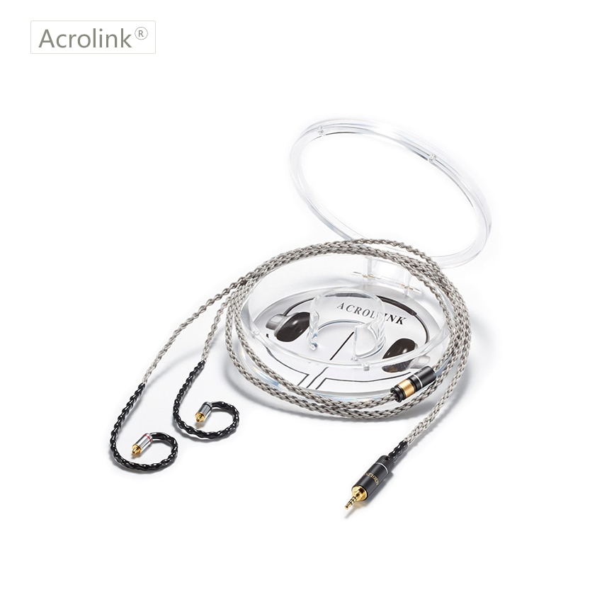
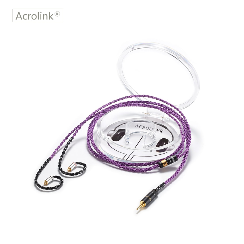
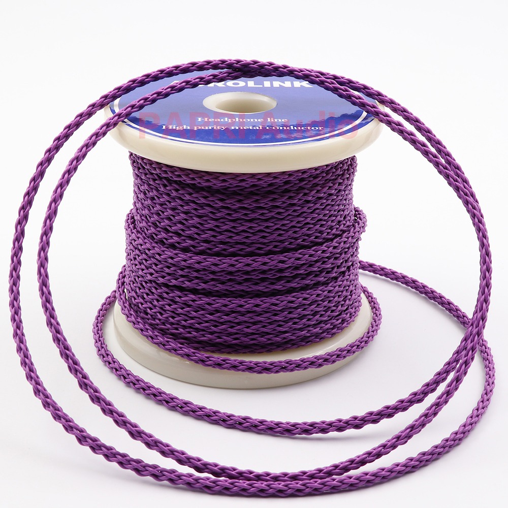
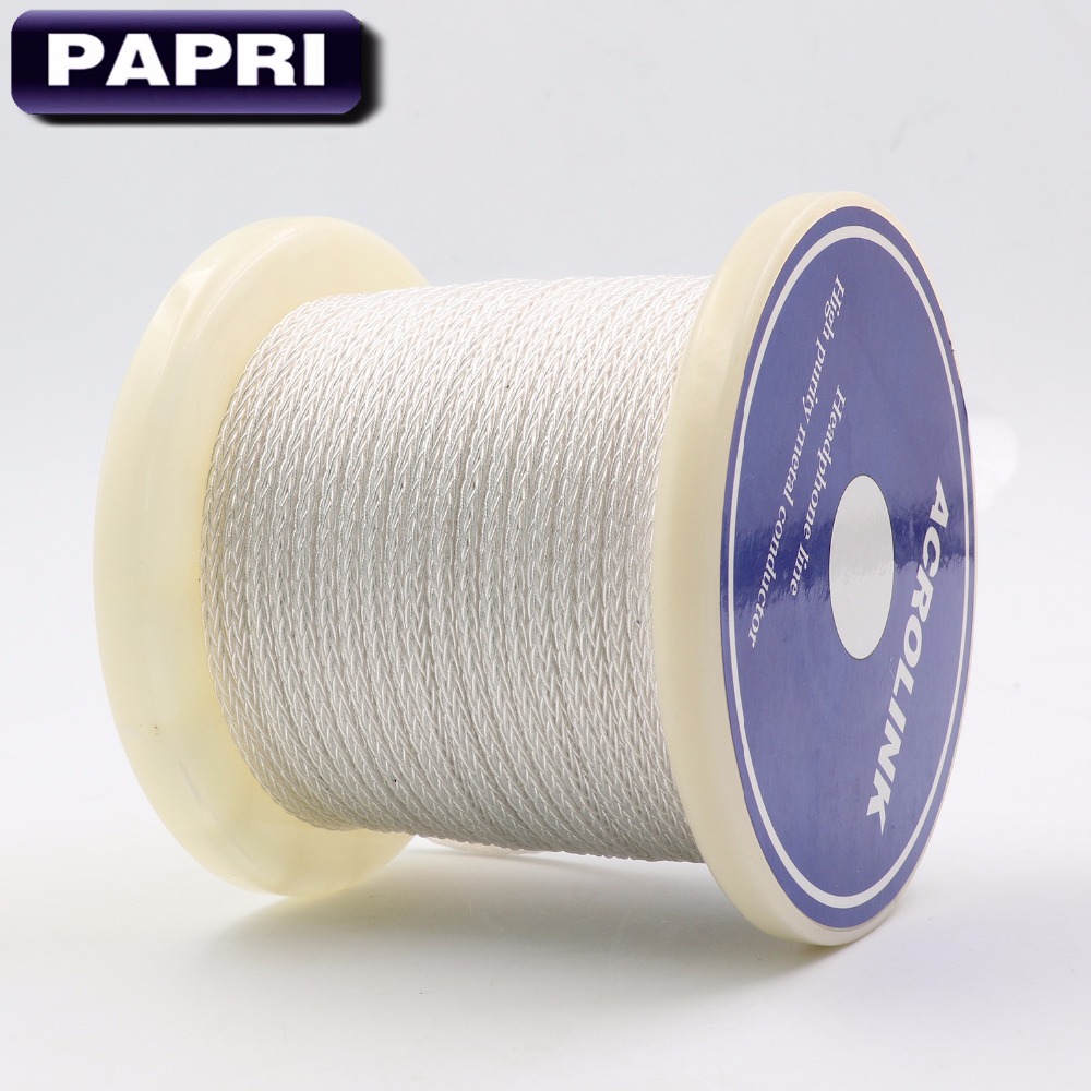
These lists pretend to be a compendium of recent cables, which provide good value (affordable decent quality). Most are chinese ("chicables").
The number preceding each cable is chosen arbitrarily as convenient identification (sorry for the "cryptic" numbers, but after watching the pics at spoiler section twice, you'll get used to the numbers of the cables you are interested of).
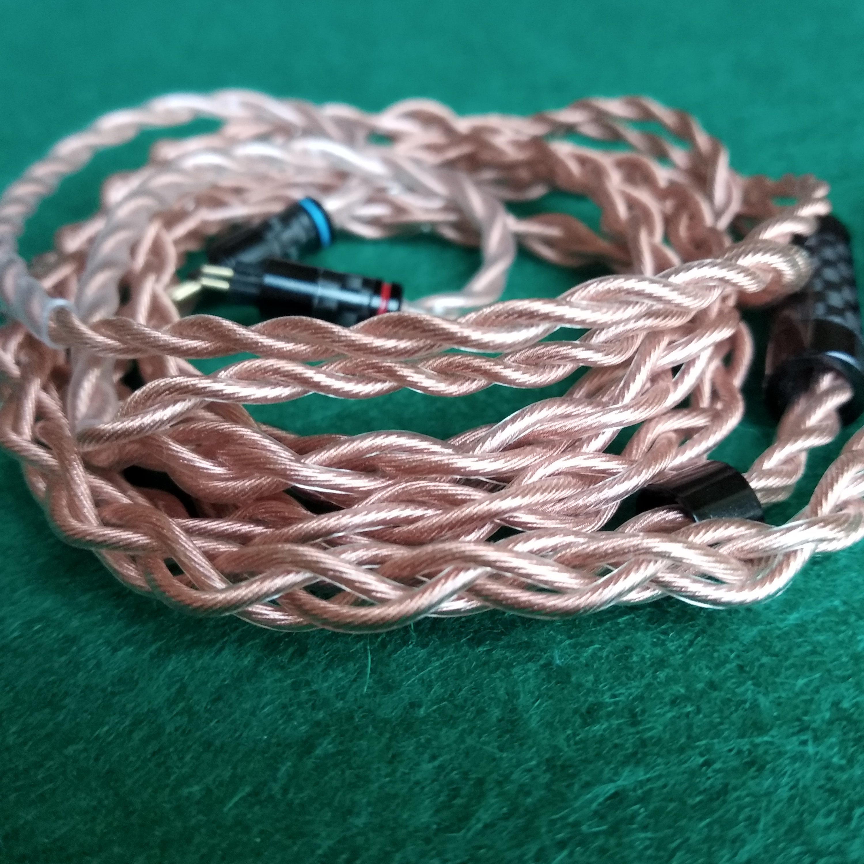
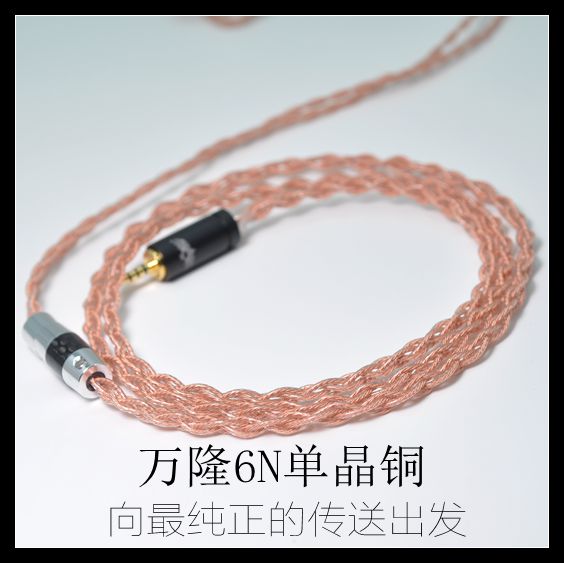
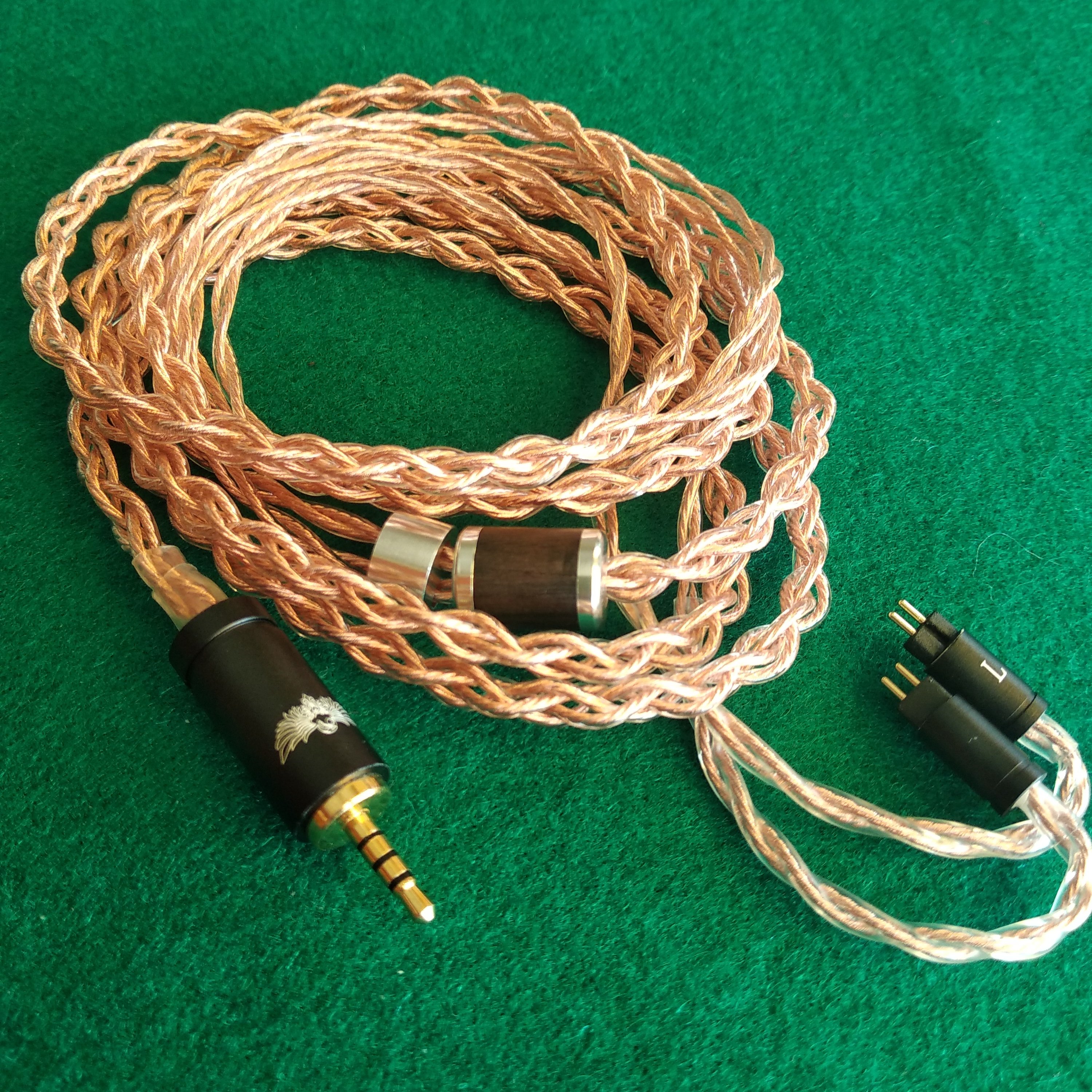
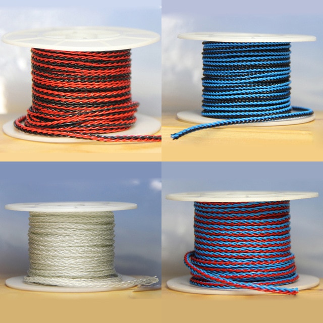
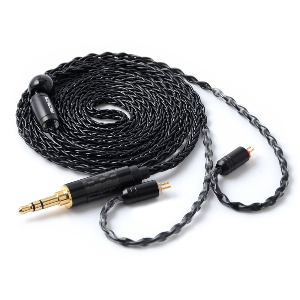
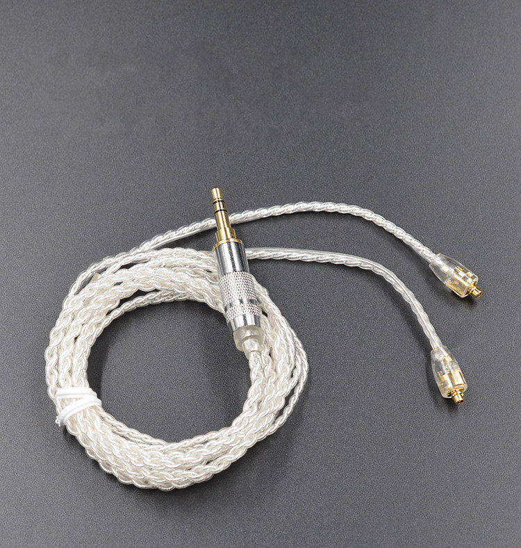
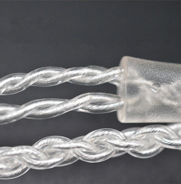
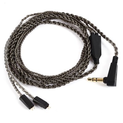
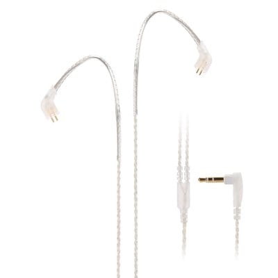
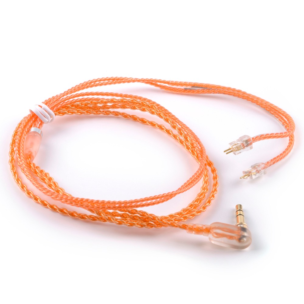
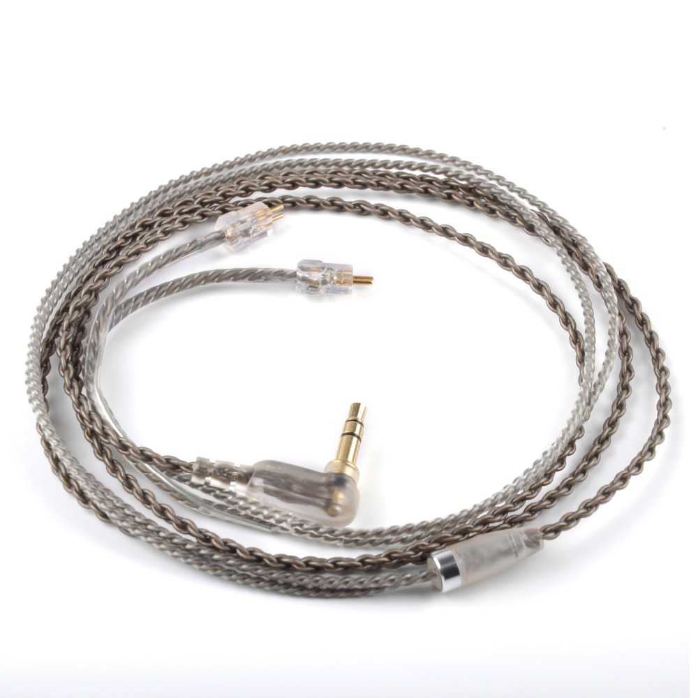
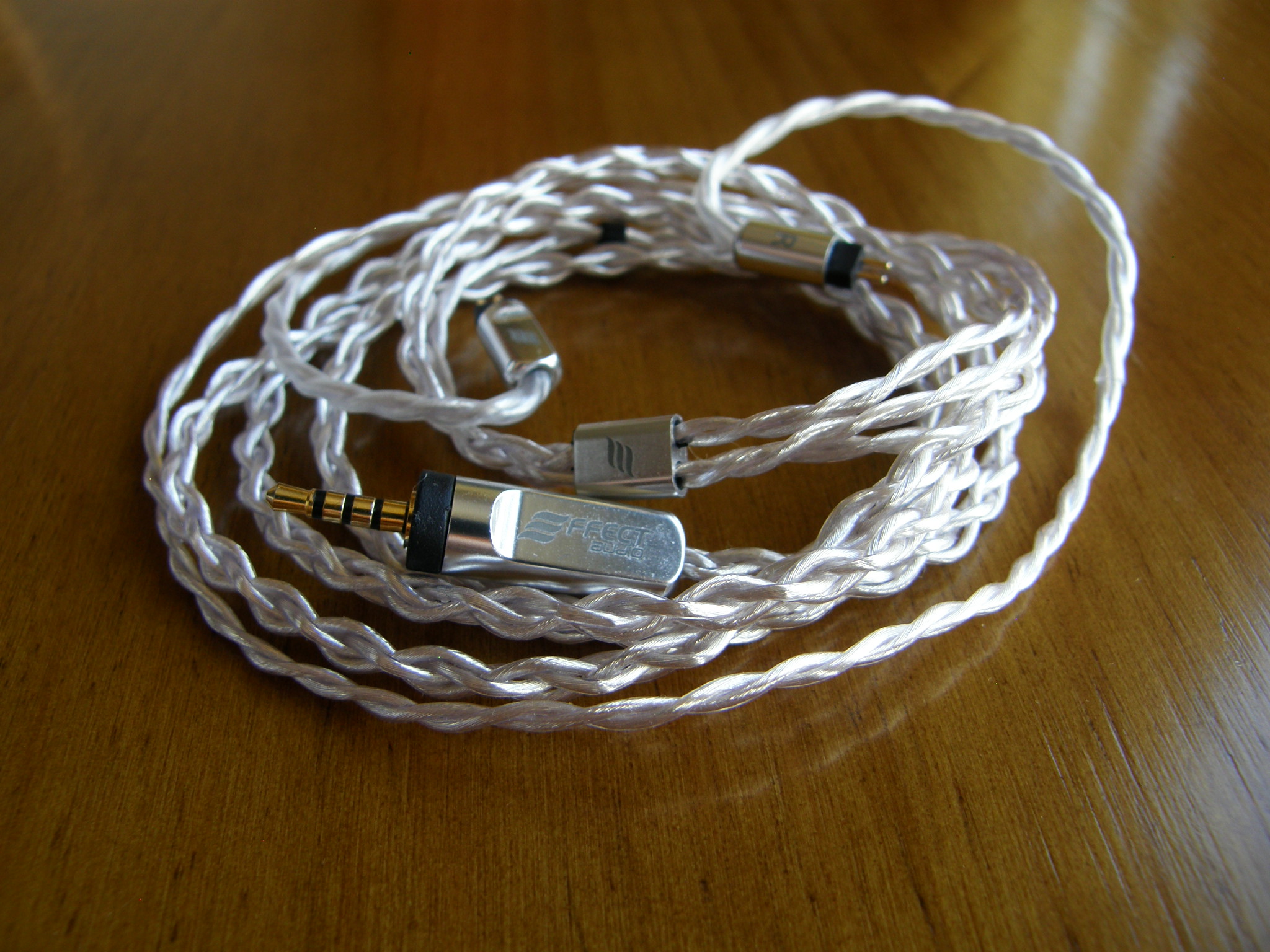
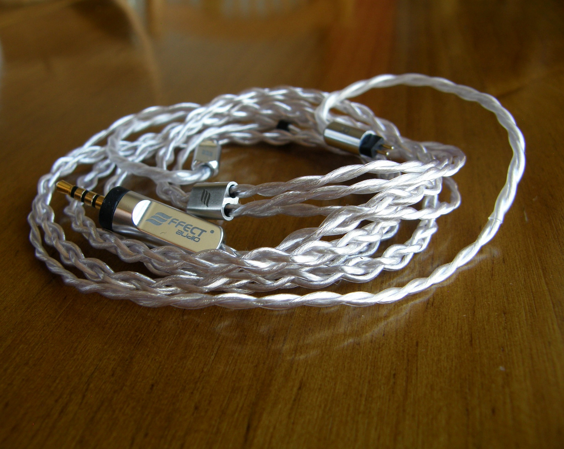
You can find pics, comments and links (no banned seller links, nor links when the cable is widely spread) at spoiler sections.
Low resistance is symptom of quality of wires, plugs, and solders (together with total thickness of the conductor, of course).
Low resistance is important to get minimum total output impedance, in order to minimize tonal alterations when using IEM with balanced armatures.
It's also convenient to decrease attenuation and to increase damping factor and efficiency.
1- BA's input impedance curve varies, mainly from upper mids to highs, while dynamic drivers show a flatter curve. Source and cable impedance curve use to be very flat. Due to the BA's impedance curve, the higher total output impedance, the higher tonal alteration. It usually makes the highs harsher, louder, but it depends of the IEM impedance curve (BA's impedance + crossovers), so there are cases where the effect is just the opposite. In general, there is coloration, unpredictable tonal alteration. Total output impedance below 1Ω, and even lower, if possible, is desirable.
2- Also, and this applies to every phones, DD and BA, and speakers, total output impedance higher than 1/8 of the phones resistance (at 1kHz), provokes tonal alteration and higher distortion, specially in lows. This is critical when using very low impedance phones (below 8Ω, for example); in this case (very low impedance phones), you can also reach actual limits of current of your source, provoking high distortion and/or clipping; the source wouldn't like this neither..
3- Also, you get better efficiency with low total output impedance. Louder volume at same voltage. This is good for energy saving, and for longevity of your source. Low output impedance increases electric damping factor, so it helps to drive hard phones.
However, we have to make some considerations about cables.
1- If your source output resistance is 15 times (for instance) higher than the resistance of the cables you are considering, the resistance of the cables becomes insignificant; the culprit of the problem, if any, will reside in your source.
2- The magnitude of the tonal alterations depends of the IEMs mainly. In most cases, the resistance differences between cables won't provoke highly noticeable tonal alteration at human registers; they'll be below 1dB, or even below 0.5dB at audible frequencies, except if we are talking about cables with resistance close or even higher than 1Ω.
It's all about proportions and perfectionism. If we keep our cable resistance lower than 300mΩ (equivalent to 28AWG copper) or 200mΩ (26AWG), most of us shouldn't notice the alterations.
Cables don't sound, they can only degrade sound more or less.
Material and quality of the conductor, plugs, and sleeves, contribute to minimize degradation.
An ideal cable wouldn't degrade sound, so you could reach the limits of your source and phones.
Usual measurements don't reveal significant differences in tonality nor distortion. But when rolling cables while listening music, many of us find differences about background noise and stage, which can affect to thickness, definition, separation, and imaging perception. They are not big differences, but noticeable. All these parameters are not easily measurable, and our brain is very special and tricky when perceiving sound.
When you plan to buy a cable, you should consider all this. If your sources and/or phones have low quality, it's absurd to get a fancy expensive cable: the bottleneck won't be in the cable.
Once you get decent quality gear, you have to remember than in audio every next upgrade is more expensive to get smaller improvement. The limit is your perfectionism grade, and your wallet.
A good idea is to keep proportion, or to pass when you know that the improvement is not worth it compared to the cost.
Link: Other considerations about capacitance, geometry, and isolation of cables
Based on my experience with Chinese cables, although there are good exceptions:
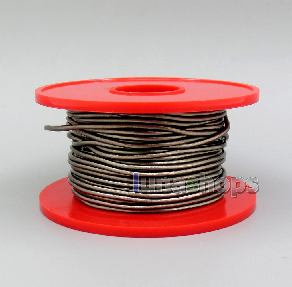
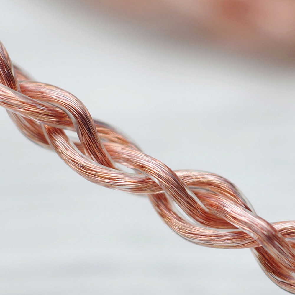
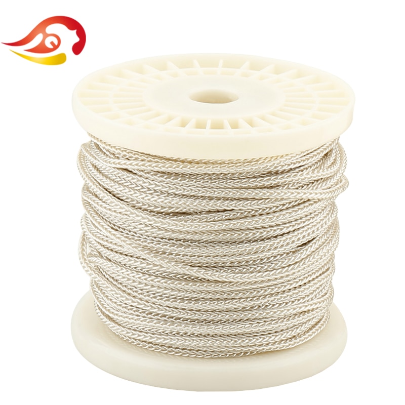
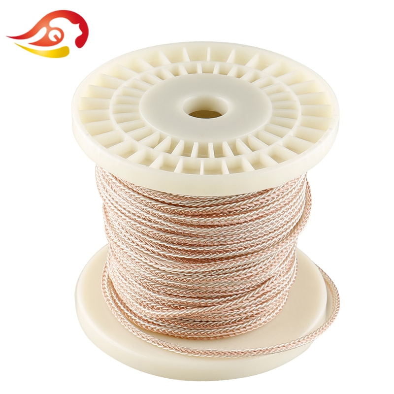
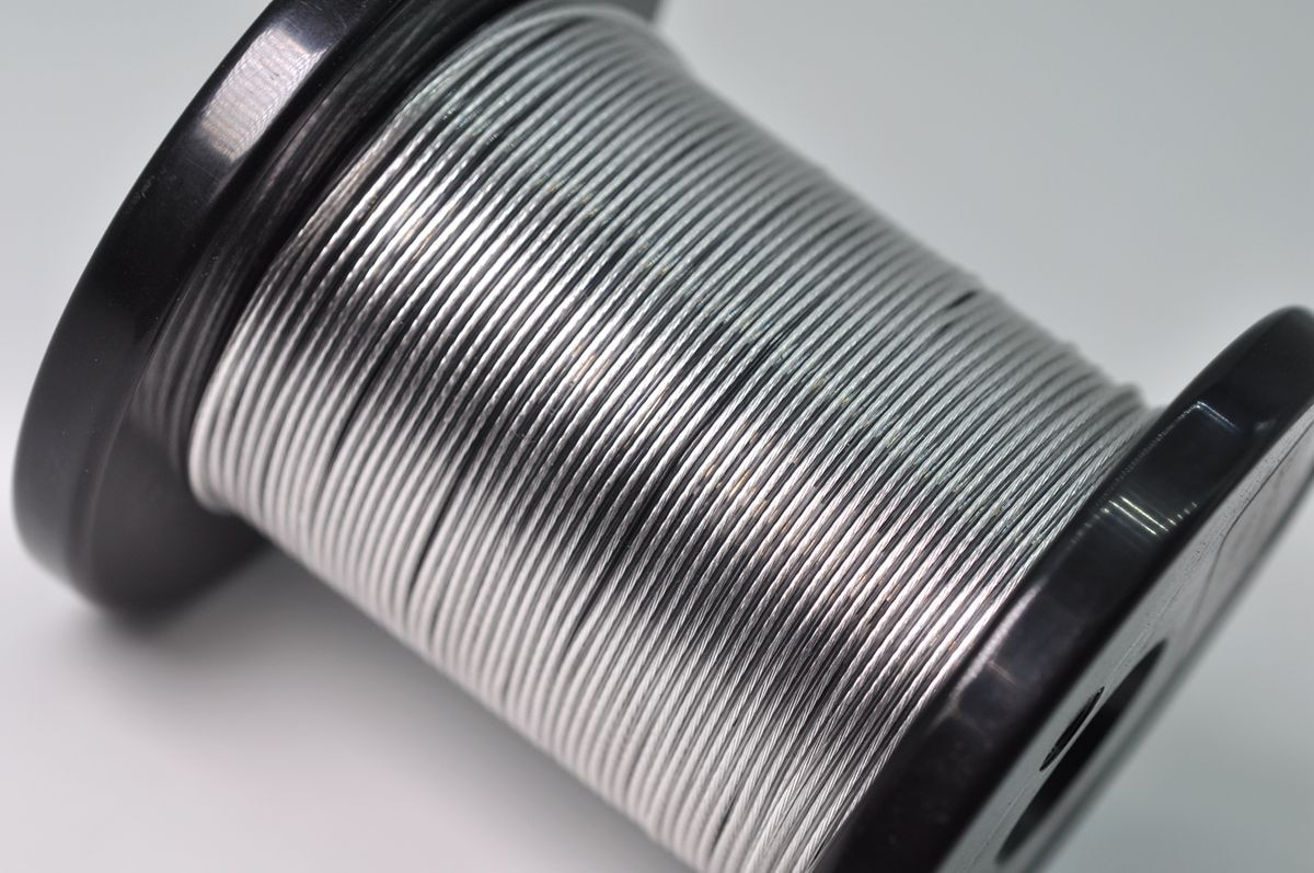
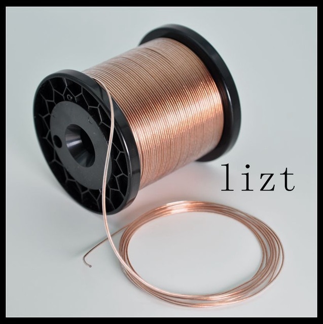
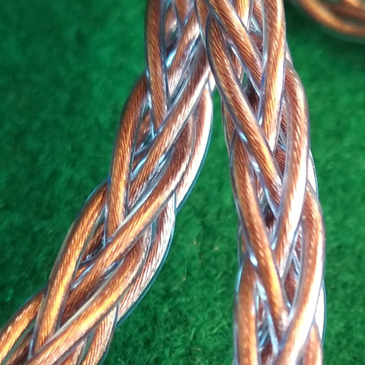
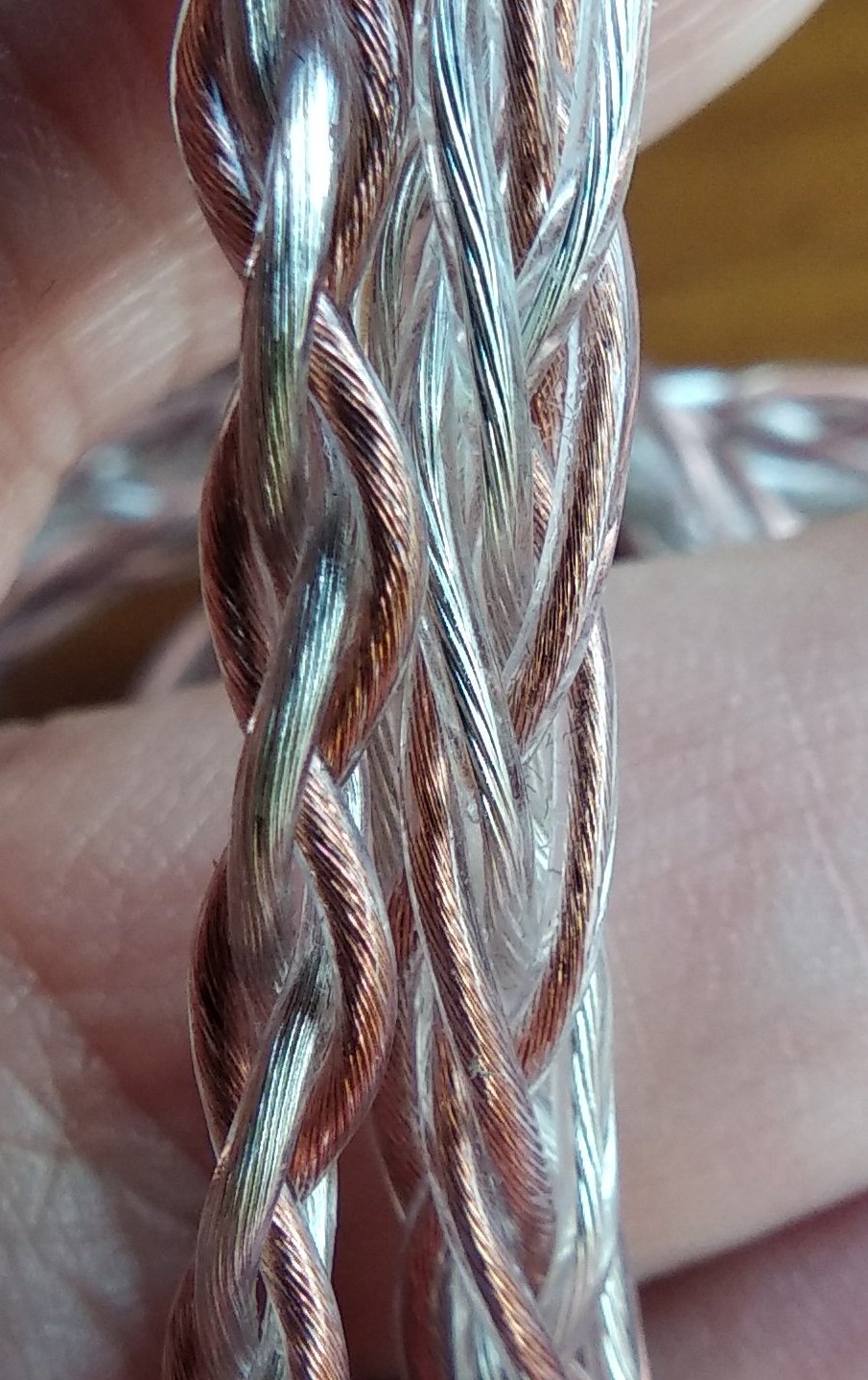
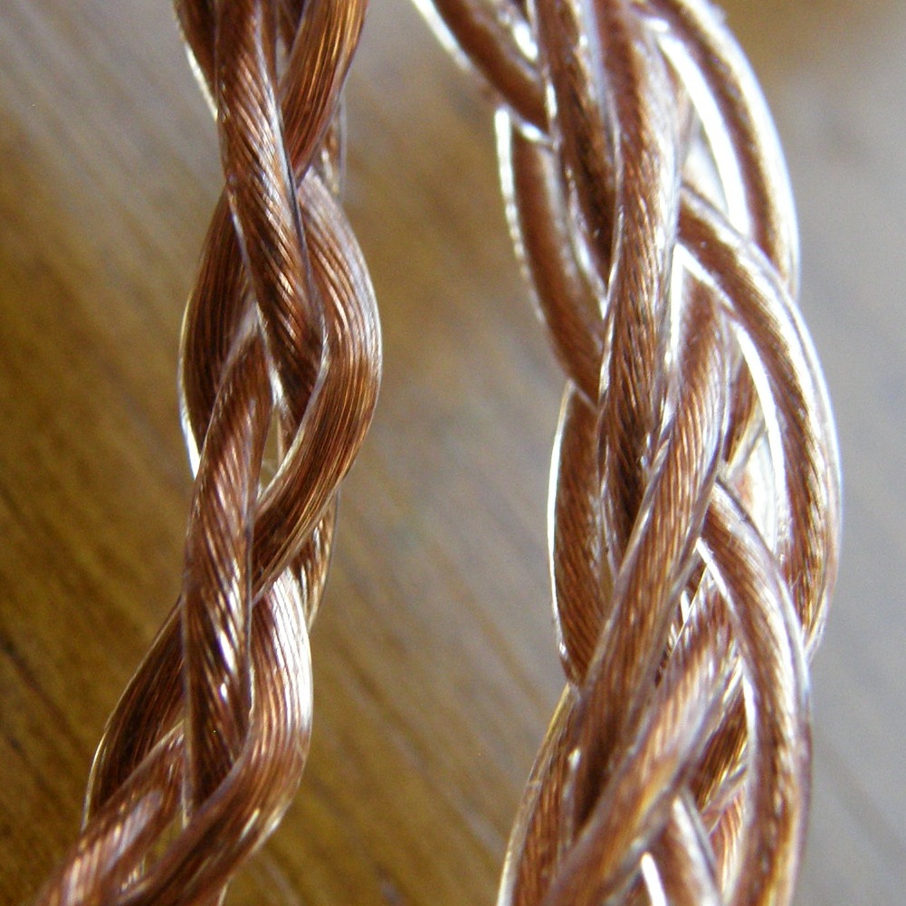
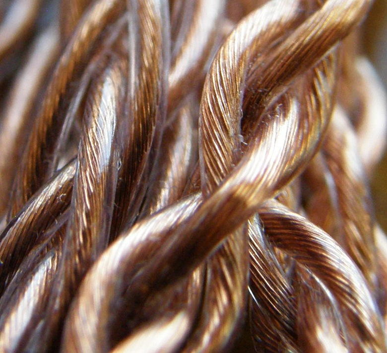
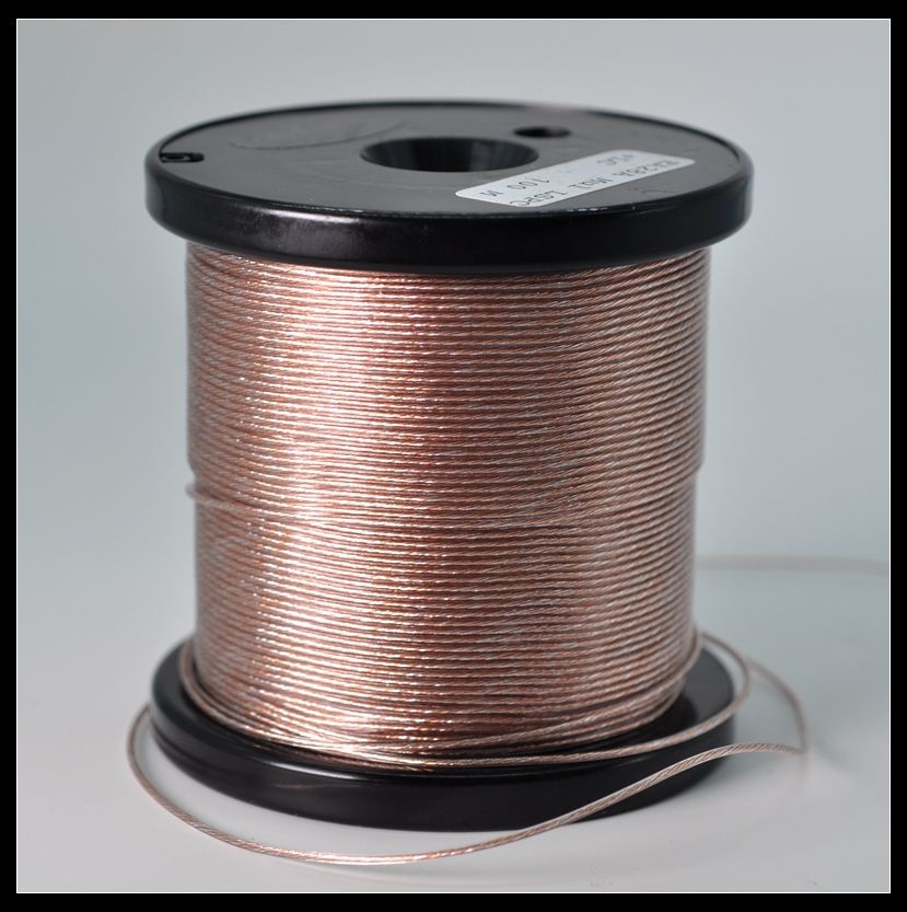
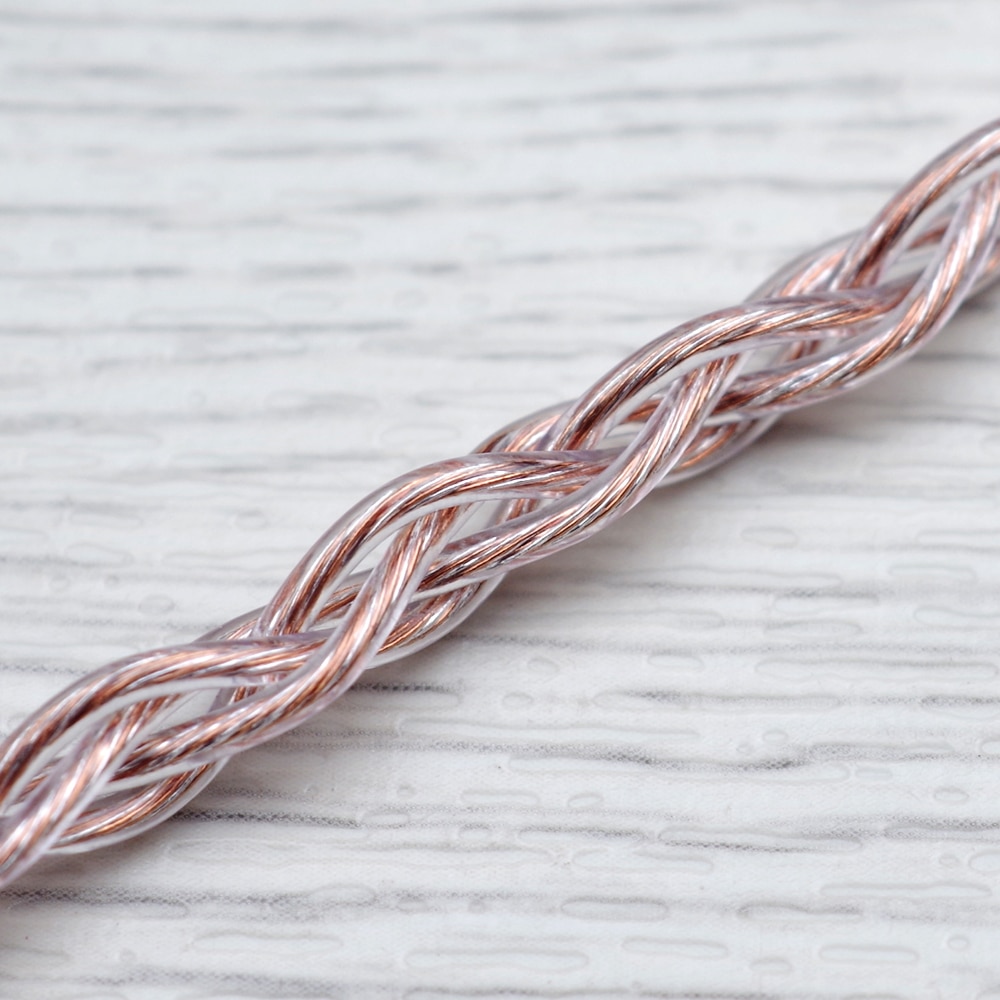
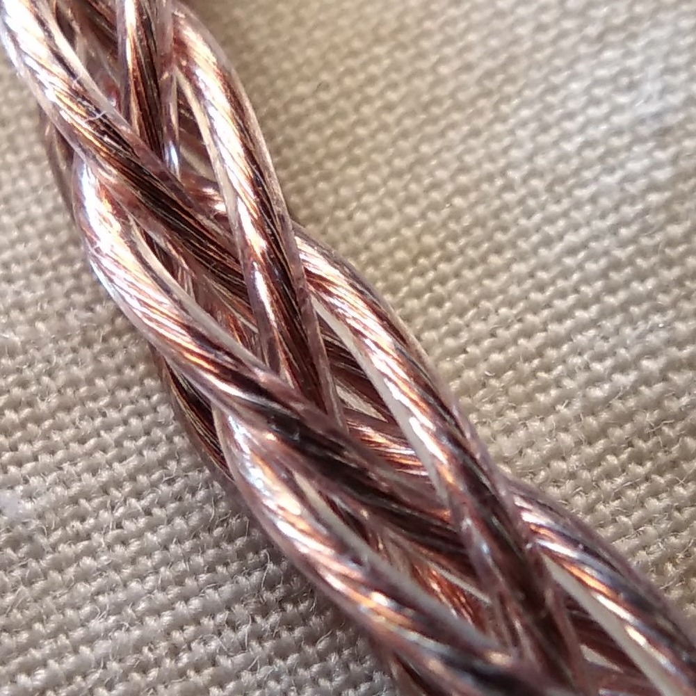
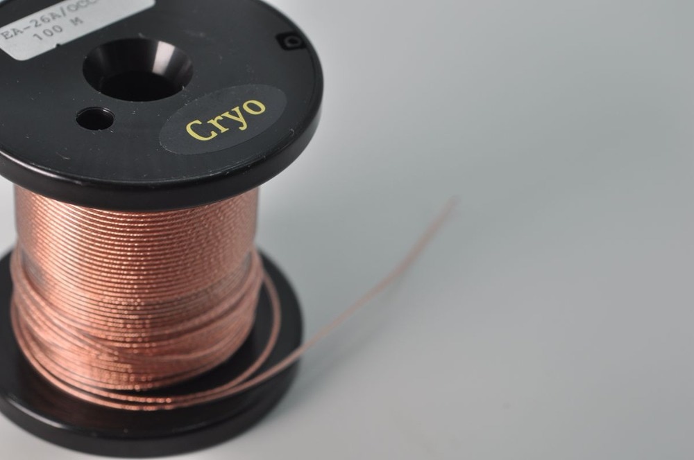
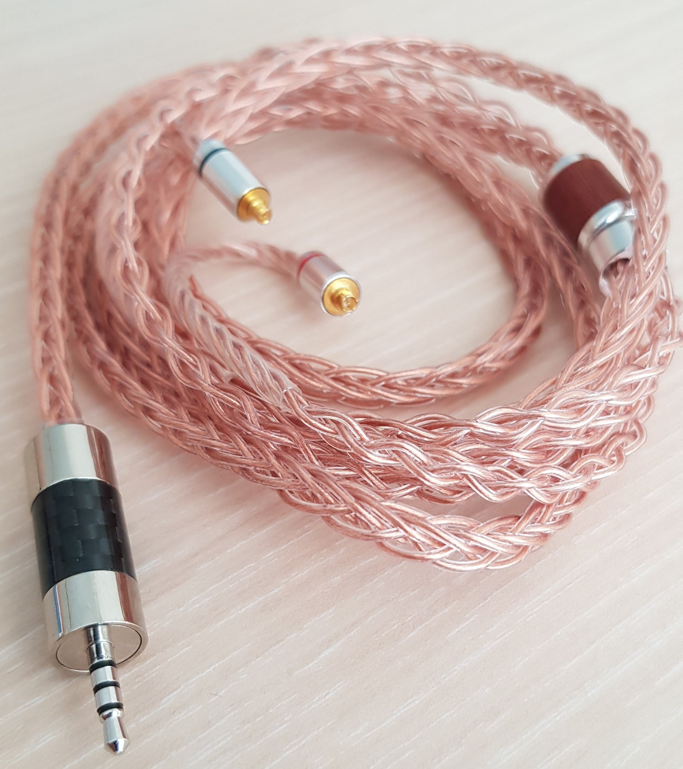
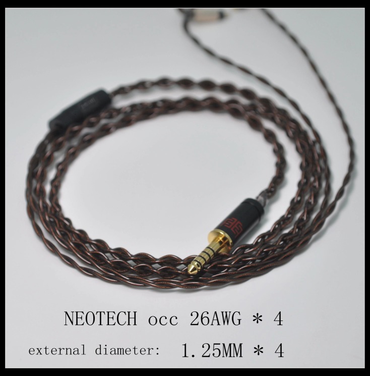
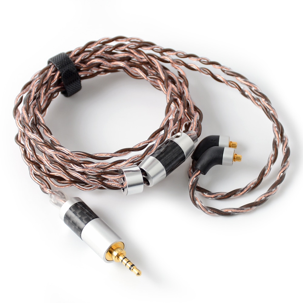
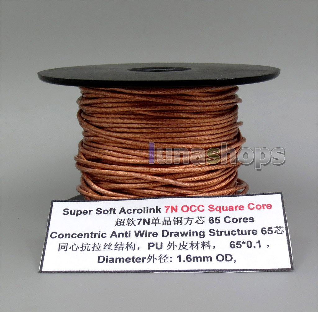
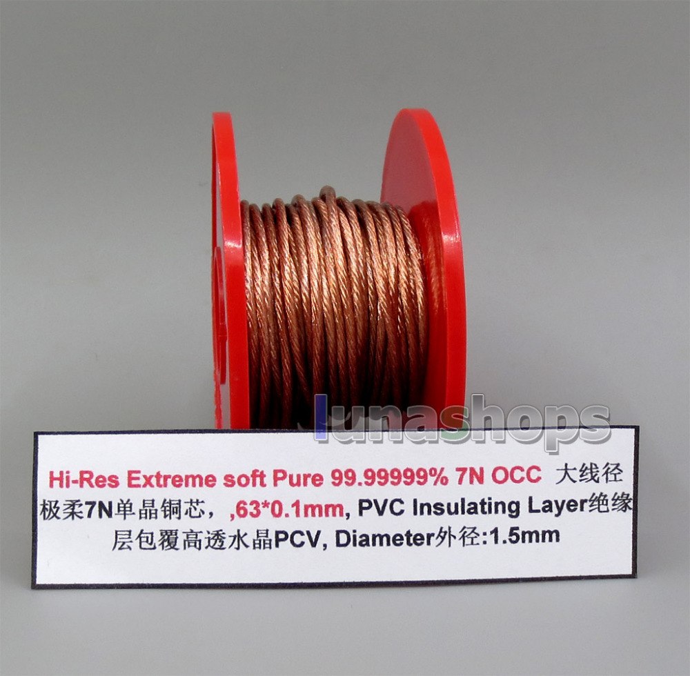
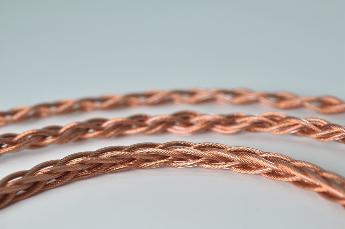
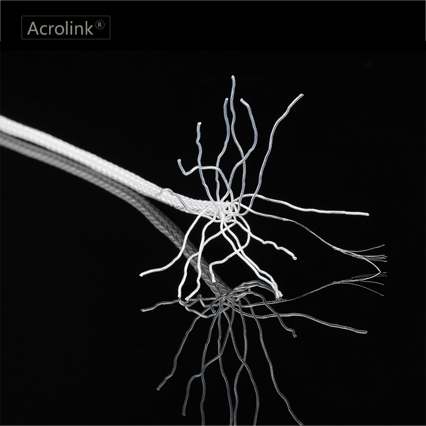
Copper
When they say high purity copper, it means simple OFC (oxygen free copper).
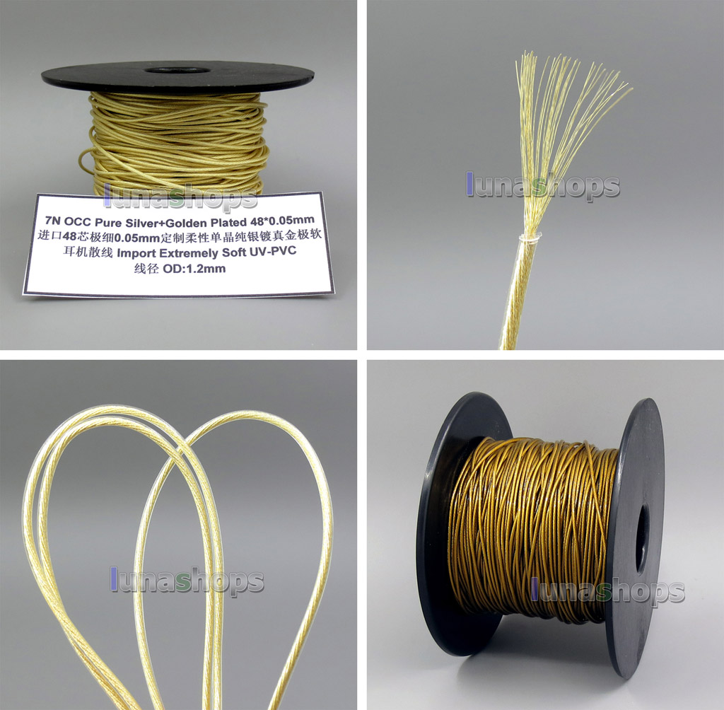
There is better quality copper: single crystal, OCC -ohno continuous casting-, and variants (UP-OCC, PC-OCC, ...), freeze treatments, and others. In theory, few boundaries in copper help to better conductivity, more linear resistance.
same with purity grade of copper (4N=99.99%, 5N=99.999%, 6N=99.9999%, 7N=99.99999%). Fewer impurities help to better conductivity, more linear resistance.
Difference of price is usually huge, compared to audible improvement. Chinese manufacturers and sellers lie frequently about the quality of the copper (specially about purity grade) and it's difficult to prove it.
So trying them is the only way to know if it's worth it for you.
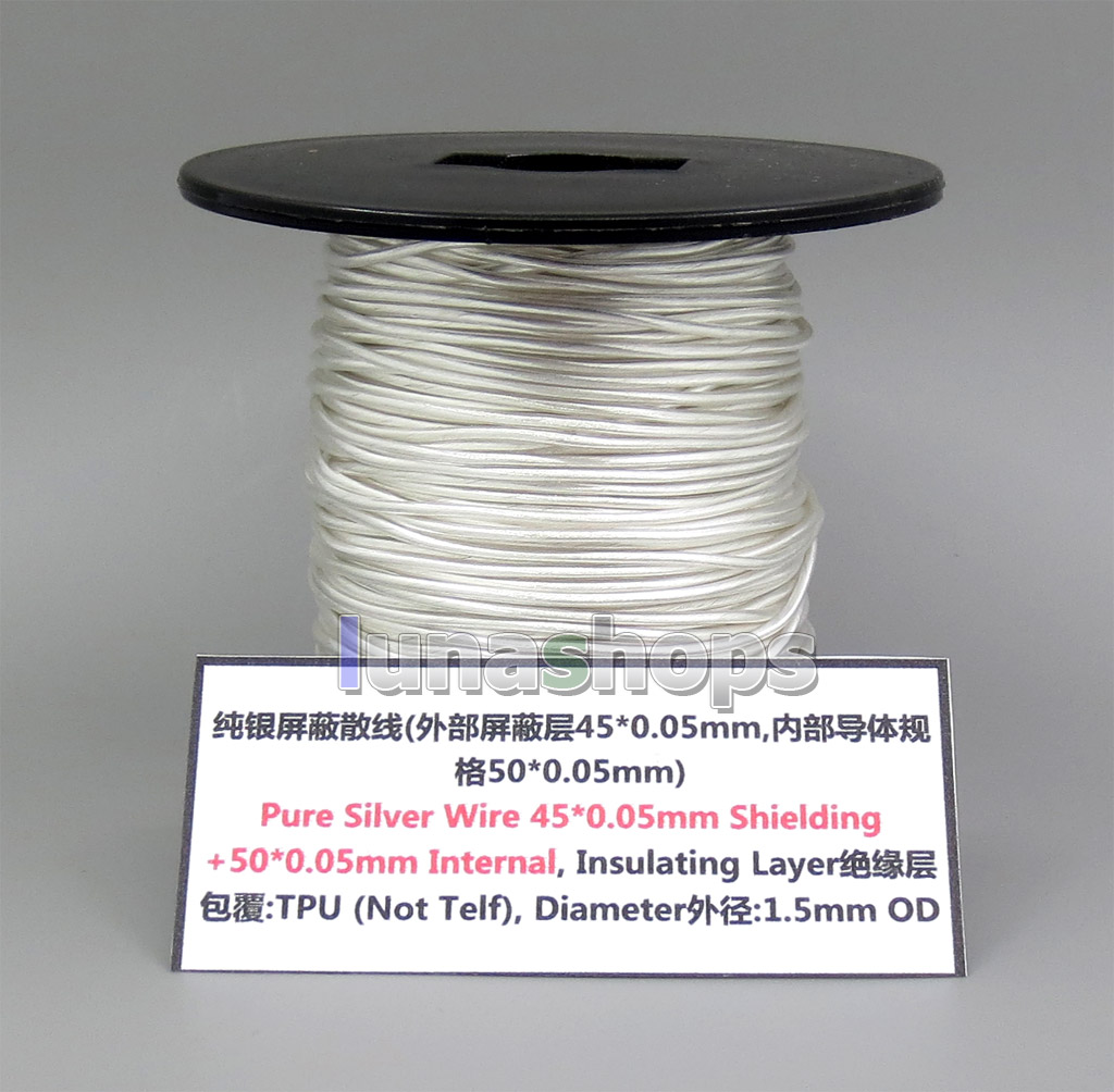
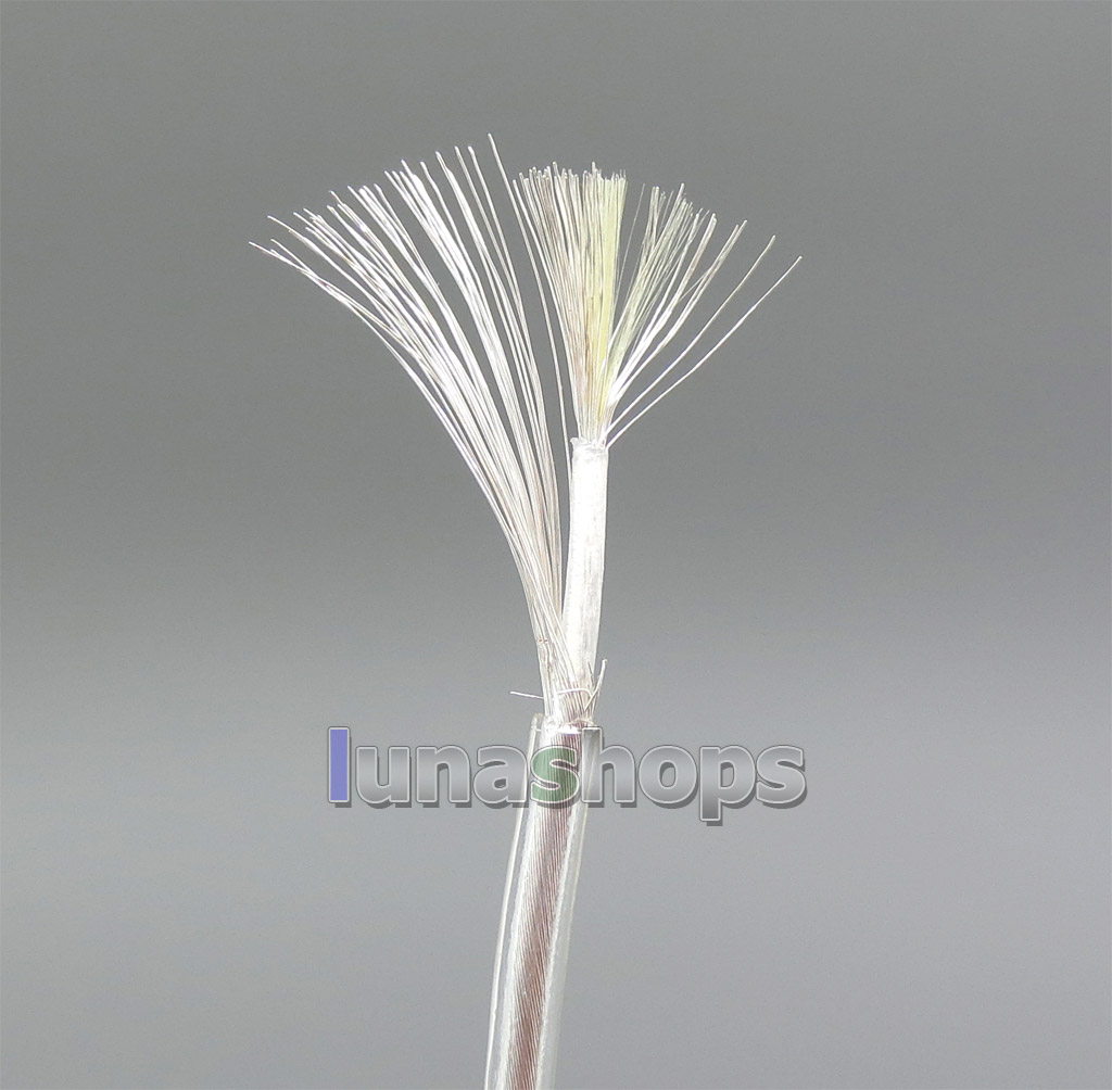
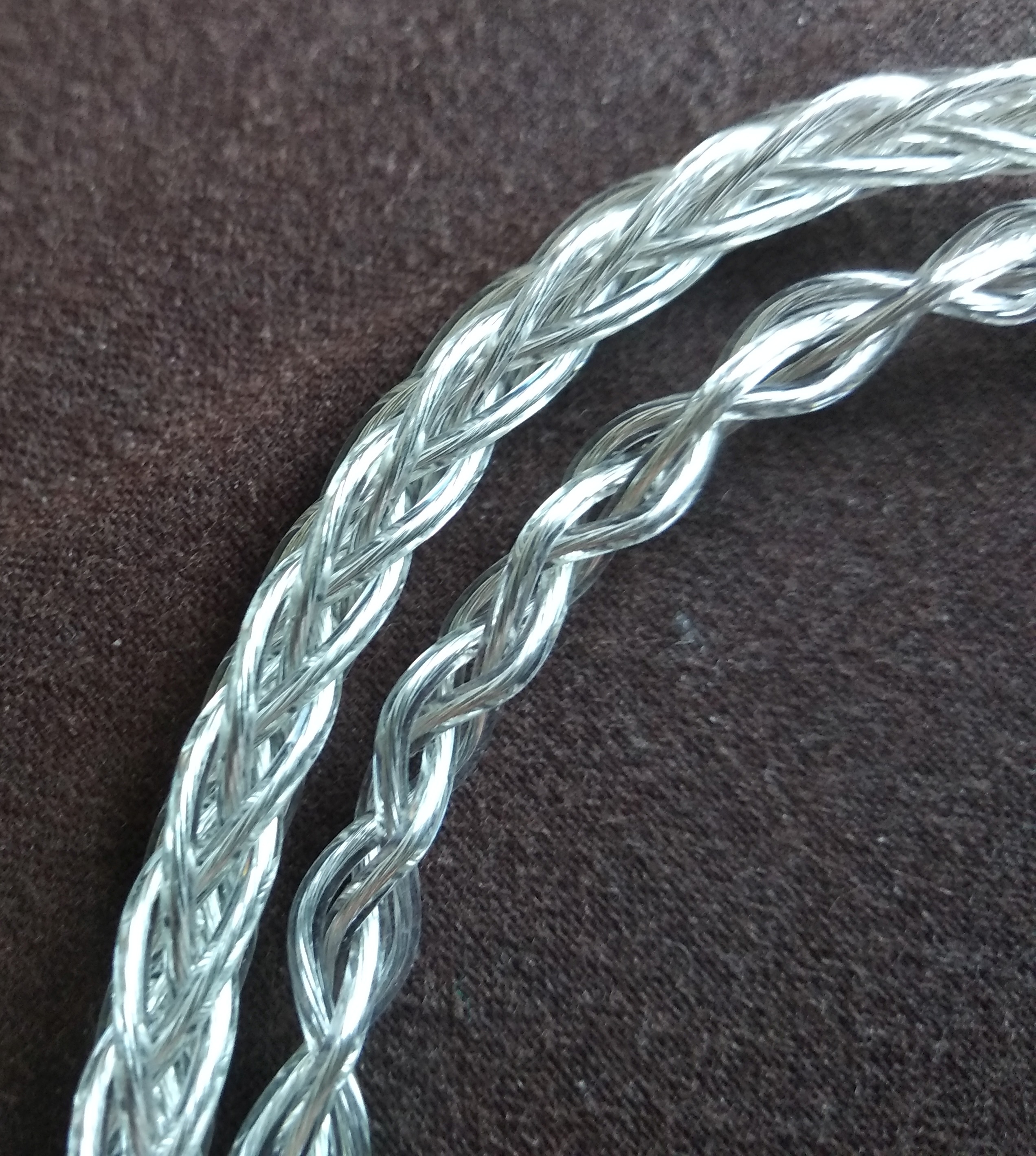
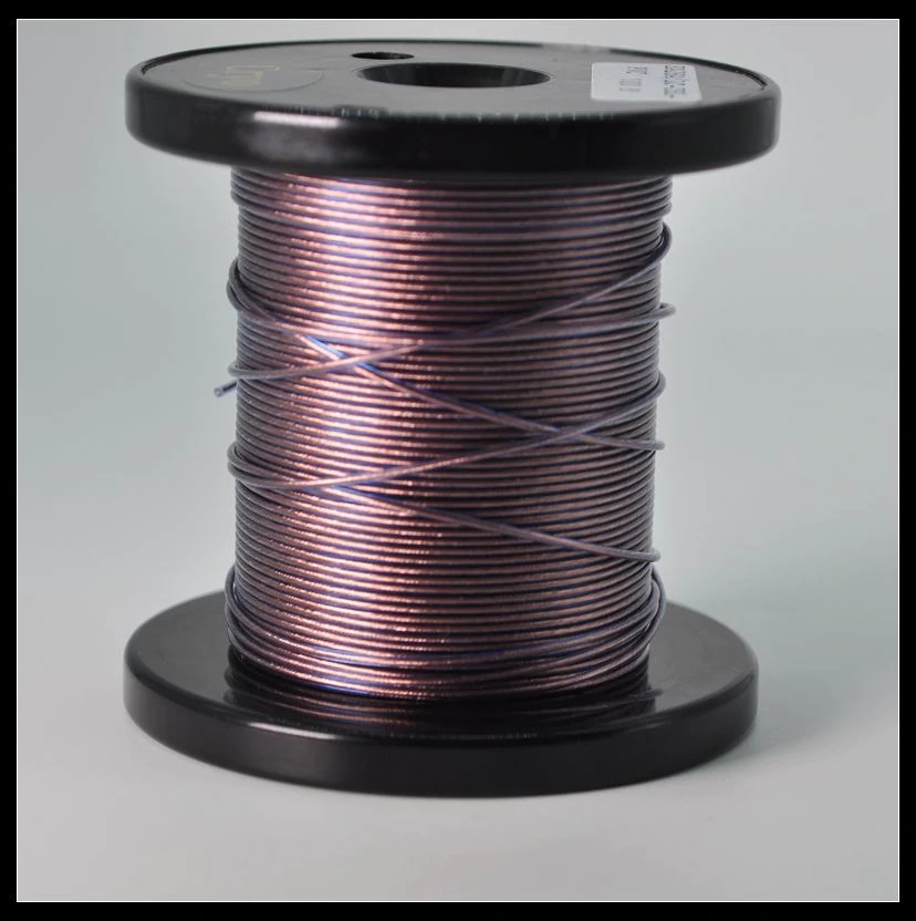
Silver
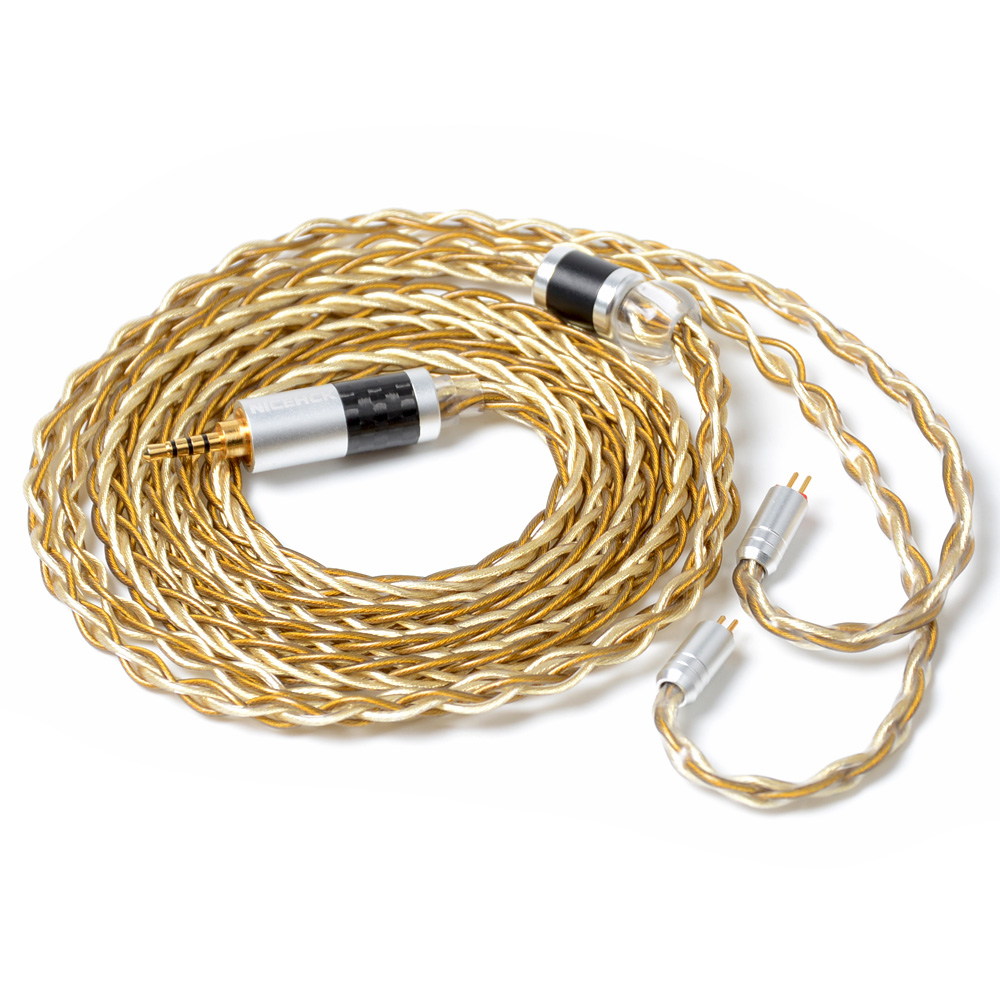
When they say silver plated copper, it is usually tin or alloy plated. When they say pure silver wire, it is pure silver plated copper wire frequently.
True silver plating raises the price considerably; and true pure silver wire is around double (or even much more) the price of true silver plated copper.
Silver is only a bit more conductive than copper. Its structure and purity could contribute to better conductivity, more linear resistance, as well.
Again, we are in the same place than before: audible improvement? At what cost?
There is some consensus about copper and silver (true silver, not tin or other alloys): copper preserves lows better, silver preserves highs better. Not demonstrated once again, but some people affirm to be able to distinguish between them.
Measurement of DC resistance of cables
1- Calibrate your multimeter.
a) Set your DMM to measure resistance, mΩ range, if available.
b) Touch the leads one against the other. Read resistance of them and note it. Do it for any leads (point, alligators, etc.) you plan to use. You only have to do this once. Choose the less resistance leads of each type available.
c) If your DMM is able to use a reference for relative measuring (REL button or similar), you can set your lead resistance as reference.
2- Measure resistance.
a) Set your DMM to measure resistance, mΩ range, if available.
b) Measure resistance (details, below).
c) If you used relative measuring, the DMM has already substracted leads resistance; if don't, you'll have to subtract it to your measurement.
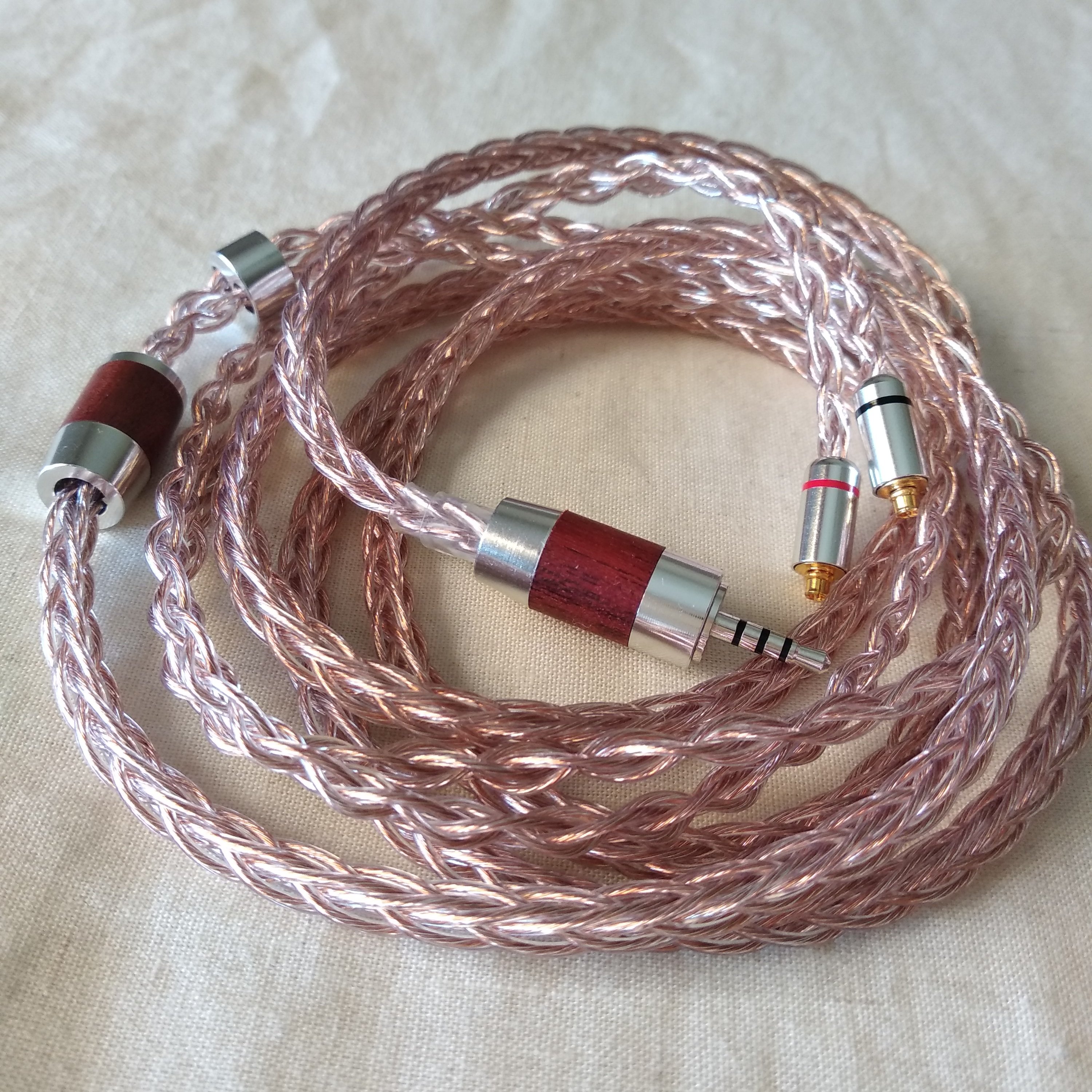
To measure 2pins TRS cables.
Tip is left signal, Ring is right signal, Sleeve is common ground. For example, to measure left path, touch or clip (I use low resistance alligator or flat clips for this, easier and more stable) the tip of the jack with one lead, and signal pin of left side with the other.
To measure MMCX TRS cables.
You can measure L/R ground easily. one lead touches sleeve part of the jack, and the other, touches the external circle of the MMCX plug.
To measure L/R signal, you have to touch the inner small pin of the MMCX plug. Depending of the leads type used, this can be complicated. point leads make it easier in this case. I use clips, so i add an MMCX to 2pins adapter of known resistance (tiny) to measure signal more comfortably.
To measure when TRRS balanced jack in the cable (2.5mm, 4.4mm; remember this is different to TRRS single end+mic jacks).
You have to know which is the balance norm used for the cable. the most used is:
tip: R-, ring1: R+, ring2: L+, sleeve: L-. (negative are cold -inverted- signals, positive are hot signals; no ground needed nor available, except a screen braid connecting the mass of the plugs in cables with RF/EMI protection).
Resolution.
10mΩ (two decimal digits) is desired (1mΩ would be superb, but not usual).
Usual cheap DMMs use 100mΩ (one decimal digit) resolution. Too much error in both leads and cable measurements, but can be used to get a gross idea.
For resistance measurements (mΩ), I use Vapcell YR1030 (https://lygte-info.dk/review/InternalResistanceMeterYR1030 UK.html , around $38), because of its resolution (~1mΩ) and because it uses 4 terminal leads (alligator clamps or probes, like showed at https://lygte-info.dk/review/InternalResistanceMeterYR1035 UK.html ); this is very comfortable: you don't have to subtract leads resistance, and measurements are more stable.
I use UNI-T UT61E for voltage (mV) and capacitance (pF) measuring.
Anyway, you can use a cheaper DMM as well. Here is an example using a $22 DMM (ZOYI ZT109, 2 decimal points at Ω, 10mΩ resolution), with very low resistance clamp leads (they didn't come with the DMM). You have to wait until reading is stable.
1. Calibration: ~10mΩ (0.01Ω) leads resistance

2. Measurement of $20 cable, 2.5mm balanced, left+ signal:


0.11Ω - 0.01Ω (leads resistance) = 0.10Ω (100mΩ).
Absolute error of this measurement: ~15mΩ
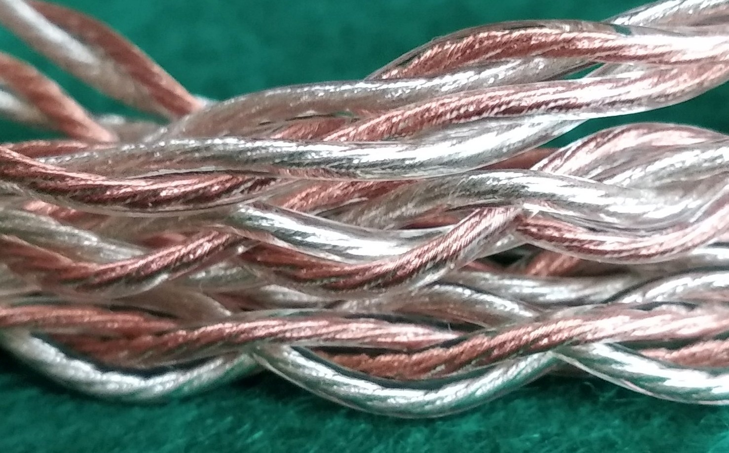
Calculation of resistance of a cable, given conductor material, structure, and length
You can read this tutorial.There are also tools in internet which make the calculations for you.
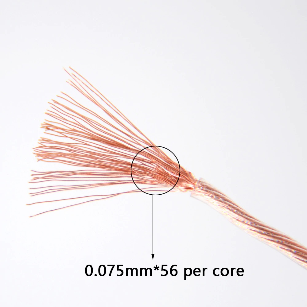
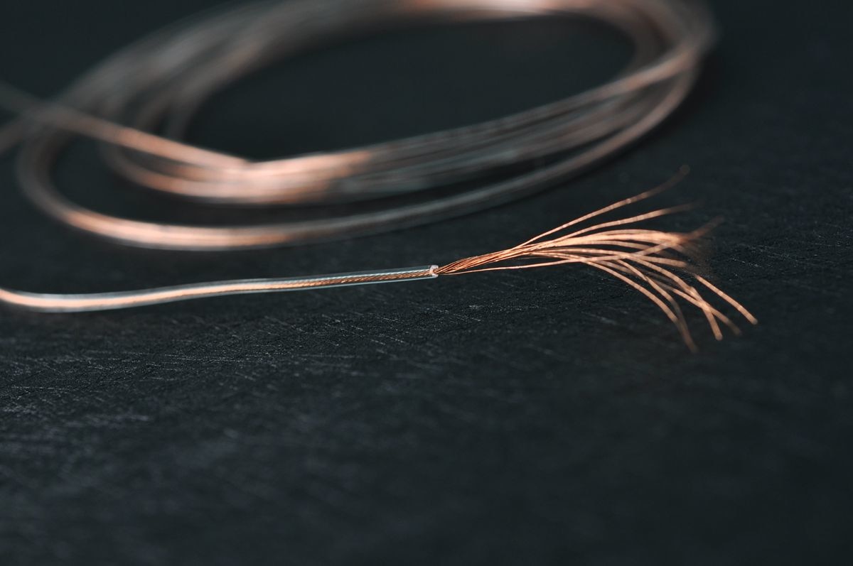
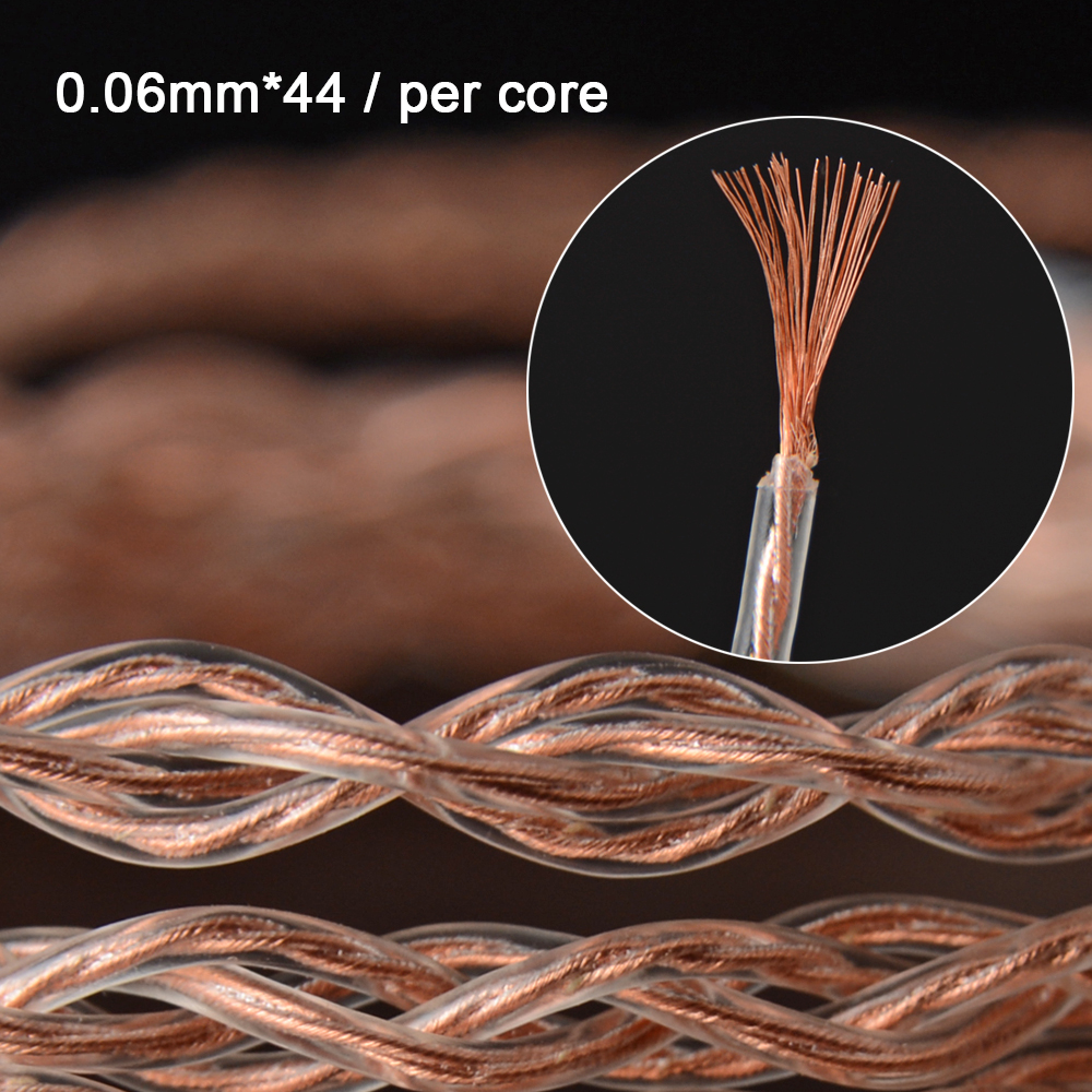
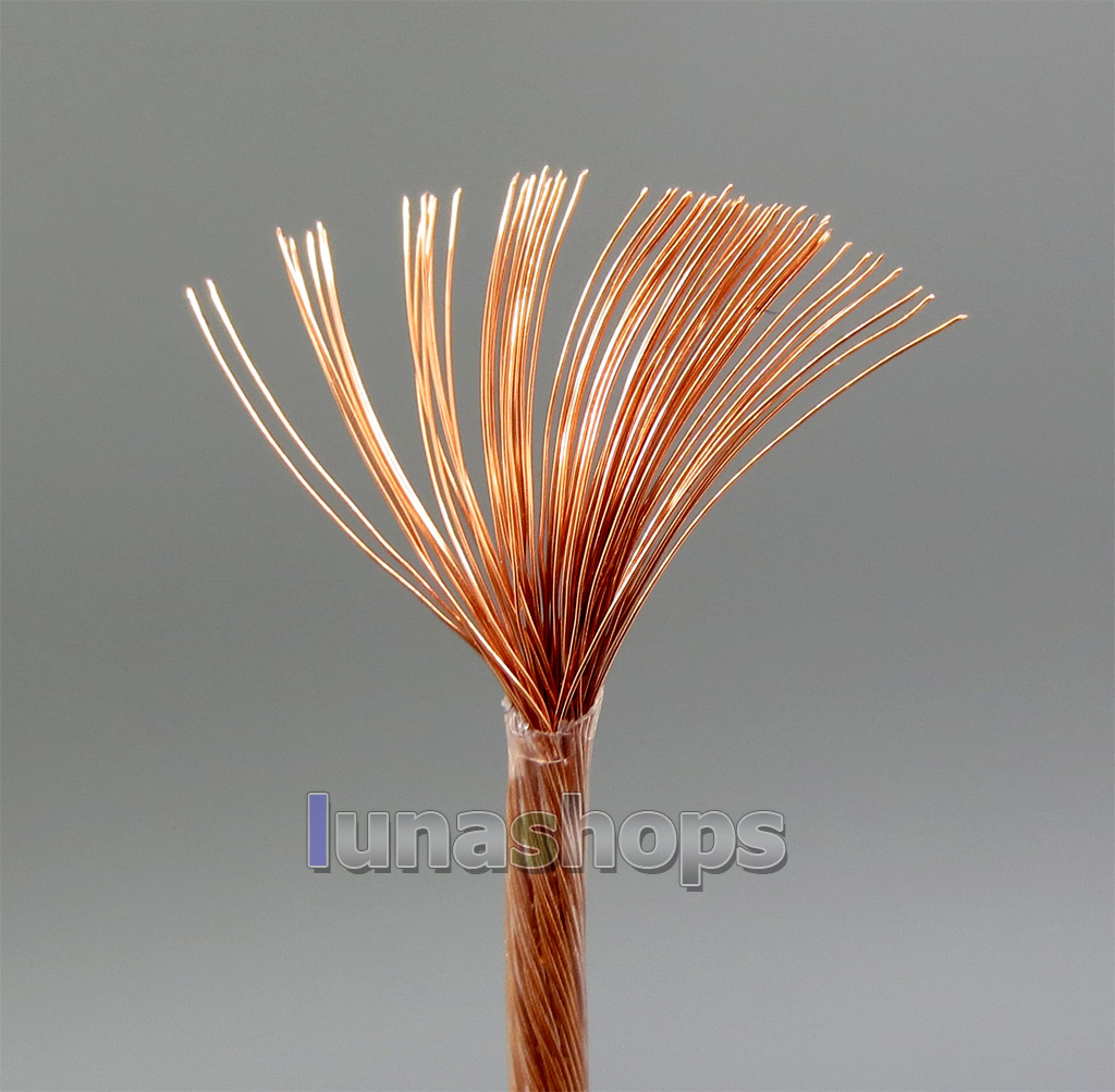
1. Calculate section of each strand (surface of a circle). StrandSection = pi * Radius * Radius. If your strand diameter is 0.04. radius is half the diameter. So StrandSection = pi * 0.02 * 0.02 = 0.0012566 mm2
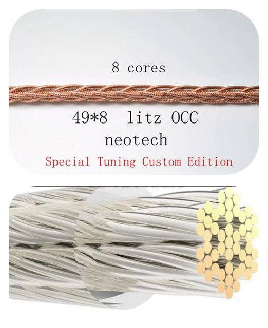
2. Calculate section of the the core. CoreSection = NumberOfStrands * StrandSection. so CoreSection = 0.0012566 * 80 = 0.1 mm2 (this is equivalent to a wire of 0.36mm diameter = 27AWG)
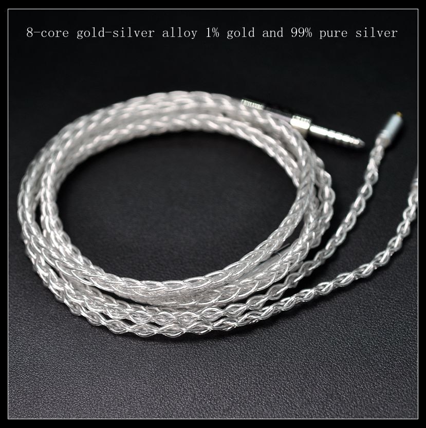
3. Calculate section of each signal. SignalSection = NumberOfCoresPerSignal * CoreSection. If your wire is 4 cores, each signal will use 1 core (2 for ground); if your wire is 8 cores, 2 cores are used per signal. Let's imagine this is your case. SignalSection = 2 * 0.1 = 0.2 mm2 (which is equivalent to 0.51mm diameter = 24AWG).
4. Calculate resistance per signal for you length.
Resistance= (MaterialResistivity / SignalSection) * Length
Here are typical resistance of some materials at 20ºC, per area of square millimeter (and conductivity is the inverse of resistivity, 1/resistivity).
..Silver 0.0159
..Copper 0.0168
..Annealed copper 0.0172
..Gold 0.0244
..Aluminum 0.0265
If your wire is copper, and your length is 2m,
Resistance = (0.0168 / 0.2) * 2 = 0.168Ω = 168mΩ.
Add plugs and solders resistance (let's say around 15-30mΩ), and your 8 cores cable of 2m will have a total resistance of around 190mΩ per signal.
Note that the difference when using pure silver is not much (around 180mΩ).
- cables below 400mΩ measurements
..............pics, comments, and links, part 1
..............pics, comments, and links, part 2
..............pics, comments, and links, part 3
..............pics, comments, and links, part 4
..............pics, comments, and links, part 5
..............pics, comments, and links, part 6
- cables for KZs (below $40, most below $25) measurements
..............pics, comments, and links, part 1
..............pics, comments, and links, part 2
- jack adapters (measurements, pics, and links)
I've created this thread because some people suggested that the measurements info should be found easier, rather than buried in posts from different threads, and because updating the info is also easier for me this way.
We can keep discussing in the low end cables thread, or KZ thread in case of cables for KZs.
But feel free to comment or discuss here as well, if you like..
Rules are the usual head-fi rules for threads.
These lists pretend to be a compendium of recent cables, which provide good value (affordable decent quality). Most are chinese ("chicables").
The number preceding each cable is chosen arbitrarily as convenient identification (sorry for the "cryptic" numbers, but after watching the pics at spoiler section twice, you'll get used to the numbers of the cables you are interested of).
You can find pics, comments and links (no banned seller links, nor links when the cable is widely spread) at spoiler sections.
Low resistance is symptom of quality of wires, plugs, and solders (together with total thickness of the conductor, of course).
Low resistance is important to get minimum total output impedance, in order to minimize tonal alterations when using IEM with balanced armatures.
It's also convenient to decrease attenuation and to increase damping factor and efficiency.
1- BA's input impedance curve varies, mainly from upper mids to highs, while dynamic drivers show a flatter curve. Source and cable impedance curve use to be very flat. Due to the BA's impedance curve, the higher total output impedance, the higher tonal alteration. It usually makes the highs harsher, louder, but it depends of the IEM impedance curve (BA's impedance + crossovers), so there are cases where the effect is just the opposite. In general, there is coloration, unpredictable tonal alteration. Total output impedance below 1Ω, and even lower, if possible, is desirable.
2- Also, and this applies to every phones, DD and BA, and speakers, total output impedance higher than 1/8 of the phones resistance (at 1kHz), provokes tonal alteration and higher distortion, specially in lows. This is critical when using very low impedance phones (below 8Ω, for example); in this case (very low impedance phones), you can also reach actual limits of current of your source, provoking high distortion and/or clipping; the source wouldn't like this neither..
3- Also, you get better efficiency with low total output impedance. Louder volume at same voltage. This is good for energy saving, and for longevity of your source. Low output impedance increases electric damping factor, so it helps to drive hard phones.
However, we have to make some considerations about cables.
1- If your source output resistance is 15 times (for instance) higher than the resistance of the cables you are considering, the resistance of the cables becomes insignificant; the culprit of the problem, if any, will reside in your source.
2- The magnitude of the tonal alterations depends of the IEMs mainly. In most cases, the resistance differences between cables won't provoke highly noticeable tonal alteration at human registers; they'll be below 1dB, or even below 0.5dB at audible frequencies, except if we are talking about cables with resistance close or even higher than 1Ω.
It's all about proportions and perfectionism. If we keep our cable resistance lower than 300mΩ (equivalent to 28AWG copper) or 200mΩ (26AWG), most of us shouldn't notice the alterations.
Cables don't sound, they can only degrade sound more or less.
Material and quality of the conductor, plugs, and sleeves, contribute to minimize degradation.
An ideal cable wouldn't degrade sound, so you could reach the limits of your source and phones.
Usual measurements don't reveal significant differences in tonality nor distortion. But when rolling cables while listening music, many of us find differences about background noise and stage, which can affect to thickness, definition, separation, and imaging perception. They are not big differences, but noticeable. All these parameters are not easily measurable, and our brain is very special and tricky when perceiving sound.
When you plan to buy a cable, you should consider all this. If your sources and/or phones have low quality, it's absurd to get a fancy expensive cable: the bottleneck won't be in the cable.
Once you get decent quality gear, you have to remember than in audio every next upgrade is more expensive to get smaller improvement. The limit is your perfectionism grade, and your wallet.
A good idea is to keep proportion, or to pass when you know that the improvement is not worth it compared to the cost.
Link: Other considerations about capacitance, geometry, and isolation of cables
Based on my experience with Chinese cables, although there are good exceptions:
Copper
When they say high purity copper, it means simple OFC (oxygen free copper).
There is better quality copper: single crystal, OCC -ohno continuous casting-, and variants (UP-OCC, PC-OCC, ...), freeze treatments, and others. In theory, few boundaries in copper help to better conductivity, more linear resistance.
same with purity grade of copper (4N=99.99%, 5N=99.999%, 6N=99.9999%, 7N=99.99999%). Fewer impurities help to better conductivity, more linear resistance.
Difference of price is usually huge, compared to audible improvement. Chinese manufacturers and sellers lie frequently about the quality of the copper (specially about purity grade) and it's difficult to prove it.
So trying them is the only way to know if it's worth it for you.
Silver
When they say silver plated copper, it is usually tin or alloy plated. When they say pure silver wire, it is pure silver plated copper wire frequently.
True silver plating raises the price considerably; and true pure silver wire is around double (or even much more) the price of true silver plated copper.
Silver is only a bit more conductive than copper. Its structure and purity could contribute to better conductivity, more linear resistance, as well.
Again, we are in the same place than before: audible improvement? At what cost?
There is some consensus about copper and silver (true silver, not tin or other alloys): copper preserves lows better, silver preserves highs better. Not demonstrated once again, but some people affirm to be able to distinguish between them.
Measurement of DC resistance of cables
1- Calibrate your multimeter.
a) Set your DMM to measure resistance, mΩ range, if available.
b) Touch the leads one against the other. Read resistance of them and note it. Do it for any leads (point, alligators, etc.) you plan to use. You only have to do this once. Choose the less resistance leads of each type available.
c) If your DMM is able to use a reference for relative measuring (REL button or similar), you can set your lead resistance as reference.
2- Measure resistance.
a) Set your DMM to measure resistance, mΩ range, if available.
b) Measure resistance (details, below).
c) If you used relative measuring, the DMM has already substracted leads resistance; if don't, you'll have to subtract it to your measurement.
To measure 2pins TRS cables.
Tip is left signal, Ring is right signal, Sleeve is common ground. For example, to measure left path, touch or clip (I use low resistance alligator or flat clips for this, easier and more stable) the tip of the jack with one lead, and signal pin of left side with the other.
To measure MMCX TRS cables.
You can measure L/R ground easily. one lead touches sleeve part of the jack, and the other, touches the external circle of the MMCX plug.
To measure L/R signal, you have to touch the inner small pin of the MMCX plug. Depending of the leads type used, this can be complicated. point leads make it easier in this case. I use clips, so i add an MMCX to 2pins adapter of known resistance (tiny) to measure signal more comfortably.
To measure when TRRS balanced jack in the cable (2.5mm, 4.4mm; remember this is different to TRRS single end+mic jacks).
You have to know which is the balance norm used for the cable. the most used is:
tip: R-, ring1: R+, ring2: L+, sleeve: L-. (negative are cold -inverted- signals, positive are hot signals; no ground needed nor available, except a screen braid connecting the mass of the plugs in cables with RF/EMI protection).
Resolution.
10mΩ (two decimal digits) is desired (1mΩ would be superb, but not usual).
Usual cheap DMMs use 100mΩ (one decimal digit) resolution. Too much error in both leads and cable measurements, but can be used to get a gross idea.
For resistance measurements (mΩ), I use Vapcell YR1030 (https://lygte-info.dk/review/InternalResistanceMeterYR1030 UK.html , around $38), because of its resolution (~1mΩ) and because it uses 4 terminal leads (alligator clamps or probes, like showed at https://lygte-info.dk/review/InternalResistanceMeterYR1035 UK.html ); this is very comfortable: you don't have to subtract leads resistance, and measurements are more stable.
I use UNI-T UT61E for voltage (mV) and capacitance (pF) measuring.
Anyway, you can use a cheaper DMM as well. Here is an example using a $22 DMM (ZOYI ZT109, 2 decimal points at Ω, 10mΩ resolution), with very low resistance clamp leads (they didn't come with the DMM). You have to wait until reading is stable.
1. Calibration: ~10mΩ (0.01Ω) leads resistance

2. Measurement of $20 cable, 2.5mm balanced, left+ signal:


0.11Ω - 0.01Ω (leads resistance) = 0.10Ω (100mΩ).
Absolute error of this measurement: ~15mΩ
Calculation of resistance of a cable, given conductor material, structure, and length
You can read this tutorial.There are also tools in internet which make the calculations for you.
1. Calculate section of each strand (surface of a circle). StrandSection = pi * Radius * Radius. If your strand diameter is 0.04. radius is half the diameter. So StrandSection = pi * 0.02 * 0.02 = 0.0012566 mm2
2. Calculate section of the the core. CoreSection = NumberOfStrands * StrandSection. so CoreSection = 0.0012566 * 80 = 0.1 mm2 (this is equivalent to a wire of 0.36mm diameter = 27AWG)
3. Calculate section of each signal. SignalSection = NumberOfCoresPerSignal * CoreSection. If your wire is 4 cores, each signal will use 1 core (2 for ground); if your wire is 8 cores, 2 cores are used per signal. Let's imagine this is your case. SignalSection = 2 * 0.1 = 0.2 mm2 (which is equivalent to 0.51mm diameter = 24AWG).
4. Calculate resistance per signal for you length.
Resistance= (MaterialResistivity / SignalSection) * Length
Here are typical resistance of some materials at 20ºC, per area of square millimeter (and conductivity is the inverse of resistivity, 1/resistivity).
..Silver 0.0159
..Copper 0.0168
..Annealed copper 0.0172
..Gold 0.0244
..Aluminum 0.0265
If your wire is copper, and your length is 2m,
Resistance = (0.0168 / 0.2) * 2 = 0.168Ω = 168mΩ.
Add plugs and solders resistance (let's say around 15-30mΩ), and your 8 cores cable of 2m will have a total resistance of around 190mΩ per signal.
Note that the difference when using pure silver is not much (around 180mΩ).
Last edited:


 ):
):