The Zishan dsd's corner
Jun 23, 2019 at 3:08 AM Post #2,386 of 3,711
the most "elegant" way to get a near 0 output impedance to drive my BAs in the best possible way
I recently modded my other DSD trying to achieve exactly that (my first DSD has x2 paralleled OPA1622 per channel, I estimate its output Z is around 3Ohm).
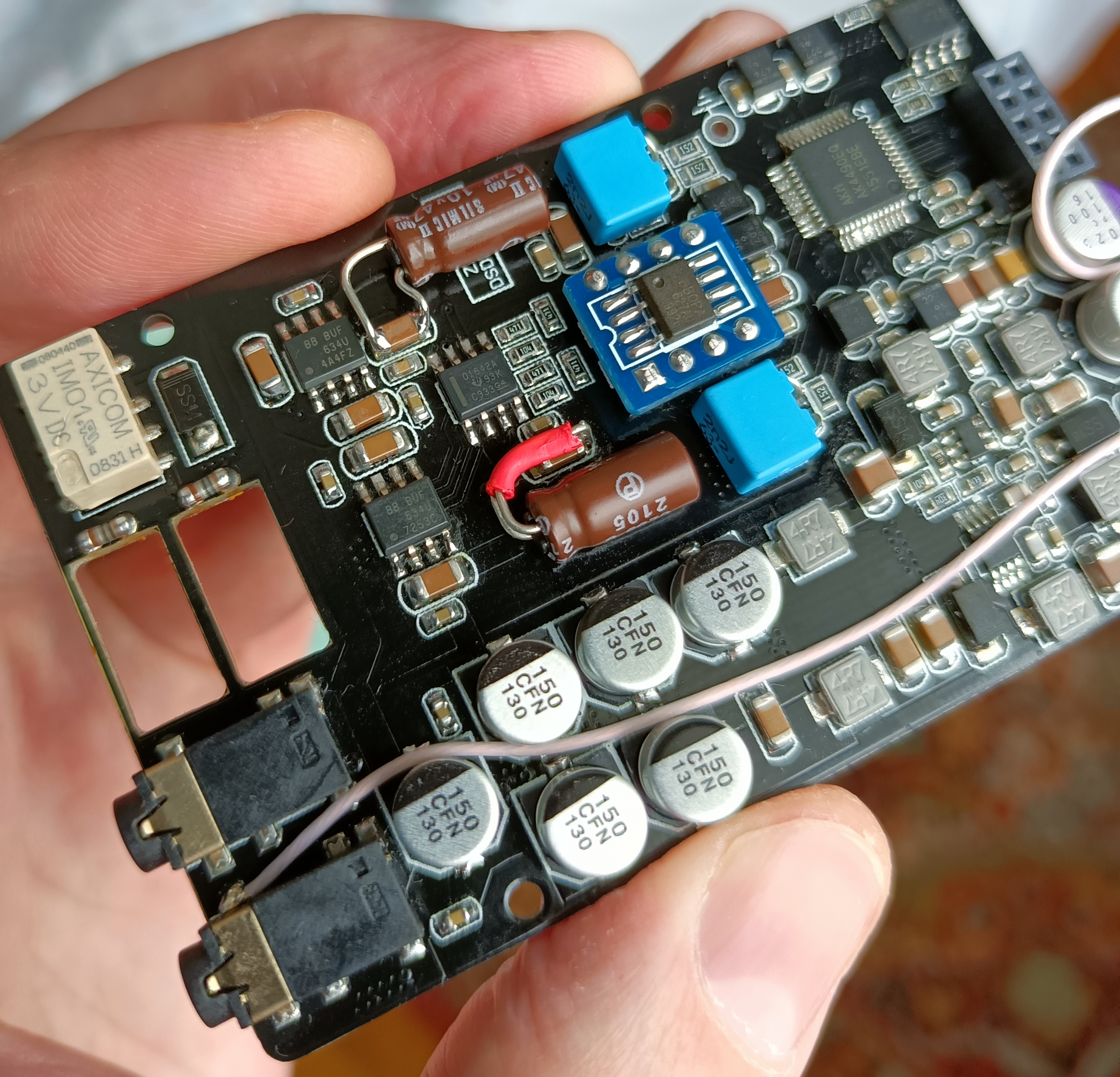
Stock DSD (assuming we are discussing AK4497 based one) in addition to output resistors has 22Ohm emitter resistors in the discrete transistor voltage follower circuit which is a little bit high (I usually see values of few Ohms (sometimes below 1Ohm actually). These are beneficial for preventing thermal-related effects, but 22ohms? Making output impedance 44Ohm effectively? Seriously? :triportsad:

I replaced those with 5.6Ohm 0805 resistors and bypassed output caps and resistors altogether, I don't hear as disturbing change in FR as with high Z output, but still evaluating this mod (including with multiple BA/low impedance IEMs). I also used bypass capacitors on these resistors (although in slightly non-convention way), this may improve output impedance further.

PS: currently listening to this mod using TF10, they are QUITE sensitive to high output Z becoming way to sizzly and lacking punch in LF, I am satisfied with how they sound right now: lows dig quite deep and there's good (but not overwhelming) sparkle in there too.
 
Last edited:
Jun 23, 2019 at 6:38 AM Post #2,387 of 3,711
Thanks Ivan, digging further down the rabbit hole, it appears to me zishan designed their z2 output stage around typical LM4562NA implementation, which is... Not a headphone amp! Ha.ha.ha. slow clap. So we have a portable player, that is not necessarily badly designed, but not really meant to drive anything below 300 ohms, typical 600 ohms.

Transportable player meant to be used as source for preamps/amps or very hard to drive headphones in other words.

So the best idea to me, if it is to be used as a direct IEMs source, would be to swap the op amp for something designed for that purpose like the TI opa1688 and replace the output caps and resistors according to typical implementation as per TI recommendations?

Too bad the Z2 thread is closed, don't mean to "pollute" the dsd one so I'll just report once it's done, as it could be beneficial for all players I think
 
Jun 23, 2019 at 11:51 PM Post #2,390 of 3,711
Even though I haven't finished setting up my workbench yet, I did go ahead this weekend, and begin disassembly of the Analog board in my DSD.
.
Will be replacing the LDO regulators; removing the AD8620ARZ op-amps, and extending the SOIC pads to DIP-8 sockets; bypassing the series resistors to the 2.5mm TRRS jack; removing the transistors that follow the socketed op-amp, and wire the socket to the 3.5mm TRS jack (bypassing the series resistors, and possibly the output capacitors).
.
.
Questions about the Relay near the 3.5mm jack - Does it protect the Amp or the Earphones? Does it do so by Opening the output to the jack, and does that Short the output of the Amp?
 
Jun 24, 2019 at 12:22 AM Post #2,391 of 3,711
Questions about the Relay near the 3.5mm jack - Does it protect the Amp or the Earphones? Does it do so by Opening the output to the jack, and does that Short the output of the Amp?
It shorts amp’s output to ground and is sitting just before the output Jack.
Warning!
Should anyone want to remove output resistors/caps this increases the output current from dip 8 opamp and burns out the traces on pcb between opamp output and feedback resistors (happened on my DSDs and few other people I know).
I cut the ground connection legs on the relay, it does produce a small click when turning on/off, but I believe still provides in-rush current protection.
 
Jun 24, 2019 at 5:11 AM Post #2,392 of 3,711
Try OPA1622 on pcb dip8 board from eBay in your z2, output caps and resistors could be removed.

According to the designer of this op amp, the perf isn't ideal on a DIP-8 socket ("Please understand that by "compromise" we're talking about a 3-6dB increase in distortion at 10kHz, it's still quite good performance and I use DIP adapters in the lab at TI for quick results if I'm not testing for absolute best performance.")

Not the end of the world but there might be better versions out there.

Overall after more research it doesn't look as trivial as I thought. I might just build an external adapter like here : https://diyaudioheaven.wordpress.com/headphones/headphone-attenuation-adapter/, and make some measurements before proceeding further and risking frying something.
 
Jun 24, 2019 at 5:29 AM Post #2,393 of 3,711
("Please understand that by "compromise" we're talking about a 3-6dB increase in distortion at 10kHz, it's still quite good performance and I use DIP adapters in the lab at TI for quick results if I'm not testing for absolute best performance.")
Fair enough.
Few points to consider:
1. ebay DIP8 version of OPA1622 not only provides virtual ground, but also bypass capacitors (although these are 1uF, I guess 0.1uF should be better) - not sure how John's adaptor looked like though...
2. Ear's sensitivity @ 10kHz and 3-6dB distortion increase (my DSD has something like 0.003% distortion, 6dB will make it 0.006% and this is 6 dB across the board)
3. Z2 schematics, which is OK, but only OK (so there's bigger fish to fry as far as distortion/noise goes).
4. It is still an awesome performance, better than 1688 (which is a bit hollow/cold sounding IMO) or pretty much any opamp you could put in that DIP8 socket.
So give it a go, even on DIP8 adaptor 1622 is awesome and is likely better than any other opamp as a HP driver :)
 
Jun 24, 2019 at 5:32 AM Post #2,394 of 3,711
Ok I'll give it a try, does your last remark "Should anyone want to remove output resistors/caps this increases the output current from dip 8 opamp and burns out the traces on pcb between opamp output and feedback resistors (happened on my DSDs and few other people I know)." apply to OPA1622 or is it safe to remove output caps/resistors? (Honnestly I don't see much point aiming for near 0 output impedance so I'd leave 2 ohms resistors there, and possibly some caps but I have to look into this)
 
Jun 24, 2019 at 5:54 AM Post #2,395 of 3,711
Ok I'll give it a try, does your last remark "Should anyone want to remove output resistors/caps this increases the output current from dip 8 opamp and burns out the traces on pcb between opamp output and feedback resistors (happened on my DSDs and few other people I know)." apply to OPA1622 or is it safe to remove output caps/resistors? (Honnestly I don't see much point aiming for near 0 output impedance so I'd leave 2 ohms resistors there, and possibly some caps but I have to look into this)
Zishan DSD AK4497 version has a discrete transistor output buffer (voltage follower), so there's no point to put OPA1622 into DSD UNLESS you bridge opamp's output all the way past output resistors to the output relay inputs (or bypass discrete buffer and put OPA1622 between DIP8 opamp output and HP out, I did it on one of my DSDs).

Z2 is a different story as DIP8 socketed opamp IS a HP driver, hence my suggestion to put it into Z2 as a quick and easy win (and it's a better option than any other opamp anyway).
This is how my own Z2 is configured, by the way.
And my AK4493 Z3.
And my GF's Z3 too.
LOL :)

PS: finished work on the Lo-Z output mod including some esoteric bypass caps between discrete transistor's emitters. TF10 is not bright anymore, sounds very, very nice and natural and organic and on par with other higher impedance IEMs I have. Downside - after capacitor mod battery life took quite a hit, which I don't mind as I simply don't have enough hours in the day to run it flat anyway.
 
Last edited:
Jun 24, 2019 at 9:28 AM Post #2,396 of 3,711
It shorts amp’s output to ground and is sitting just before the output Jack.
Warning!
Should anyone want to remove output resistors/caps this increases the output current from dip 8 opamp and burns out the traces on pcb between opamp output and feedback resistors (happened on my DSDs and few other people I know).
I cut the ground connection legs on the relay, it does produce a small click when turning on/off, but I believe still provides in-rush current protection.

When you say "provides in-rush current protection", do you mean between the battery and the higher voltage switching power supply for the Analog circuits?

Since I'm going to be moving my DSD to a larger housing (to hold larger op-amps, capacitors, and battery), I think my solution will be to remove the output jacks that are on the circuit board, and install higher quality jacks in the case, wired directly to the op-amps, and isolated from the board traces. That way, the relay can still perform its in-rush protection, and not affect the audio circuits.
 
Jun 24, 2019 at 10:12 AM Post #2,397 of 3,711
I didn't saw the circuit, but from what Ivan said, I think the relay shorts 3.5mm sound output to ground to protect headphones during power on. If we remove the output resistors, the output will be short circuited with zero resistance to ground during startup.

-EDIT-------------------------------------------------------------------------------------
(About a different subject)

In my DSD there was one 0.1uF capacitor connected to stm32 Vcap1 (pin 48) and another 0.1uF cap to Vcap2 (pin 73), but when the stm32 internal 1.2V voltage regulator is used the capacitors should be 2.2uF each, so I changed them.

We can see these recommendations and were these caps connect in the schematic in STM32F74xxx datasheet pag.95 "power supply scheme". The schematic shows that this regulator and these caps, power the cpu, ram, flash ram and IO, almost all stm32.
Vcap.JPG

-EDIT-------------------------------------------------------------------------------------
(About a different subject)

I contacted the Administrator and the Z1 and Z2 threads are open again:
https://www.head-fi.org/threads/new-zishan-z1-dsd-player-thread.844417/
https://www.head-fi.org/threads/bra...-link-to-order-firmware-update-page-1.854463/
 
Last edited:

Users who are viewing this thread

Back
Top