The "Lovely Cube" Headphone Amp (Lehmann Black Cube Linear Clone)
Feb 16, 2011 at 6:33 PM Post #466 of 1,624


Quote:
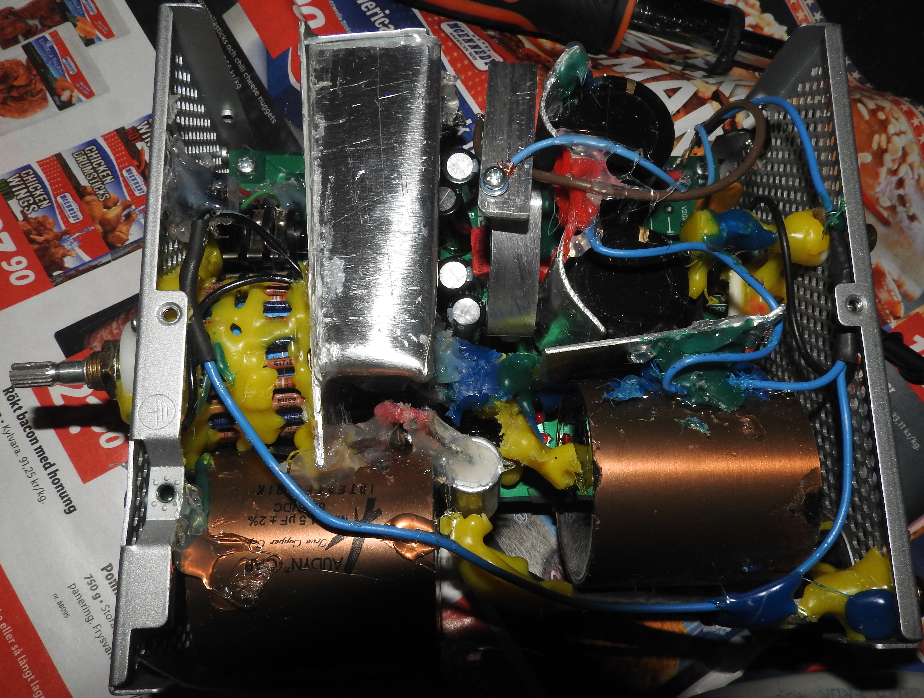
Awesome job fitting those trim pots in! How did the yellow tantalums you have in there affect the sound?


Usually, capacitors in supply region also affects the sound.  Polystyrene has more air and mild presentation, very fast and has precision. MKC has strong mids and "in your face" presentation but tends to mild things. Good MKP posses precision and bigger and (very clean) power than polystyrene but it is not so wide. MKT has power like MKP but harsh and sterile presentation (MKP is better). Tantalum capacitors? It is pure power cap, with direct presentation and it demands something in parallel....
 
It is good to put 10uF or even 22uF in Vadj circuit of regulator. It gives better noise rejection and stability. In regulator output (Vout) circuit it is good to put the smallest cap (that you can without putting circuit into oscillation).
 
BUT HERE we have 470uF electrolytic capacitors after regulator and close before transistors. So capacitors mentioned before (story about MKP, MKT, MKC etc...) do not affect sound too much in this case...
 
 
Electrolytic 470uF capacitors represent main power reservoir for output. They collect (suck) power directly from regulators much faster that headphones can spend. They collect already "cleaned" power (small voltage jumps are cleaned with Vout caps). Bypassing 470uF capacitor will mean that you "clean" power once again. Too much voltage "cleaning" leads to artificial and "boring" sound.
 
If you remove Vout capacitors and put them in parallel with 470uF capacitors then you can have bigger influence on sound. But also might put circuit into oscillation. Without oscilloscope this is not worth doing. It is not safe.
 
Removing 470uF capacitors will give you (according to some people) the best sound, in a way of sound stage, dynamic and speed. I tried that, and it is true (for driving ATH).
 
But this involves weak bass and total absence of  "punch and grunt" for "more demanding" headphones like AKG...
 
Feb 16, 2011 at 10:53 PM Post #467 of 1,624
Bla, what voltage rating is that tantalum? Because those things are priceyyyyy!
 
Perhaps we should start a new thread: "Modding your Lovely Cube!". 
biggrin.gif

 
I can't even keep up with all of this info. being thrown around.
 
Feb 17, 2011 at 2:38 AM Post #468 of 1,624


Quote:
Bla, what voltage rating is that tantalum? Because those things are priceyyyyy!
 
Perhaps we should start a new thread: "Modding your Lovely Cube!". 
biggrin.gif

 
I can't even keep up with all of this info. being thrown around.


10uF, 25V
 
Pricey but not like other capacitors... :)
 
http://cgi.ebay.com/12pcs-Kemet-Tantalum-Radial-Capacitor-10uf-35v-/120558841969?pt=LH_DefaultDomain_0&hash=item1c11ddf071
 
 
For the same price, two MKC or MKP would have 10 times lower capacitance. :)
 
Feb 17, 2011 at 9:23 AM Post #469 of 1,624
Hi all,
 
I got my preassembled LC from Stephen 2 days ago with dual OPA627 class A 3.49mA bias option. It sound really good and I really like it.
 
I have had a problem though. I asked for a stepped pot in place of the typical Alps 50k pot. When I received the LC, the pot looked warped, i.e. not perpendicular to the front panel and when turning it you could see it did not "turn round". Quite odd and annoying for the meticulous guy that I am while dealing with my gear.
 
So as I asked to get the 50k Alps anyway in the package, I went on desoldering the odd pot and soldered the proper Alps in place. I am not skilled at soldering and it took me a few tries not to get cold solderings but I finally got them acceptable and continuity check was OK. So I powered it, and tried it (with my Apple iPod earbuds just to be safe) and my problem is that it seems that the pot it now fully up all the time. It has no action at all, sound is loud full time.
So in place of a pot with warped nut I now have a nice looking pot with no action... Talk about a good move !
 
So I yet checked the pot it self and I get good resistance readings (0 to 50k Ohms) on both channel just like on the stepped one. I am clueless now, what do you think I should check next ?
My tools are as follows : digital multimeter, soldering iron and my eyes...
 
Help very much appreciated as my now 2 days old LC is just waiting for an intervention right next to me with its guts out... 
 
Thanks for reading.
 
Feb 17, 2011 at 10:14 AM Post #470 of 1,624


Quote:
Hi all,
 
I got my preassembled LC from Stephen 2 days ago with dual OPA627 class A 3.49mA bias option. It sound really good and I really like it.
 
I have had a problem though. I asked for a stepped pot in place of the typical Alps 50k pot. When I received the LC, the pot looked warped, i.e. not perpendicular to the front panel and when turning it you could see it did not "turn round". Quite odd and annoying for the meticulous guy that I am while dealing with my gear.
 
So as I asked to get the 50k Alps anyway in the package, I went on desoldering the odd pot and soldered the proper Alps in place. I am not skilled at soldering and it took me a few tries not to get cold solderings but I finally got them acceptable and continuity check was OK. So I powered it, and tried it (with my Apple iPod earbuds just to be safe) and my problem is that it seems that the pot it now fully up all the time. It has no action at all, sound is loud full time.
So in place of a pot with warped nut I now have a nice looking pot with no action... Talk about a good move !
 
So I yet checked the pot it self and I get good resistance readings (0 to 50k Ohms) on both channel just like on the stepped one. I am clueless now, what do you think I should check next ?
My tools are as follows : digital multimeter, soldering iron and my eyes...
 
Help very much appreciated as my now 2 days old LC is just waiting for an intervention right next to me with its guts out... 
 
Thanks for reading.


Are soldering pins on your pot clean?
 
You have to measure resistance between connections like stated on the picture. Also with a few different pot positions. If resistance does not exist or it is always the same value:
 
1. Pot has been shorted.
 
2. Solder suddenly connected two pins (pot - IN and pot - OUT) and now, pot is bypassed.
 
http://img248.imageshack.us/i/lovelycubepcb02.jpg/
 
Feb 17, 2011 at 10:36 AM Post #471 of 1,624
Thanks for answering with clear instructions !
 
The pot pins were not that clean but I put some solder on it before soldering to the board (don't know the English term when you apply a thin solder layer on metal).
 
I measured resistance from the exact points you describe on the picture and I get varying values as it should be. Approx same value on both channels I should say.
 
I know I messed up my solderings at first but now the readings are OK and resistance is varying depending on the pot rotation so it means that the solderings are right ? Right ?
 
Any other reading I could take ?
 
Thanks a million for helping me out
 
Feb 17, 2011 at 1:07 PM Post #472 of 1,624
So here I am with a fixed LC :)
 
I got back to Stephen and he provided tremendous support with descriptive tests to do and all. Unbelievable at past 1:00AM for him !!!
 
My problem was that for some reason I had broken the Alps common ground connection so it was just a matter of bridging 2 pins to a ground point and voilà ! Back up and running.
 
I now have a nice LC with engraved aluminum front plate (first one or only one ?), sounding great and with a nice and smooth pot.
 
Thank you BlaBlaBla for your help too !
 
Feb 17, 2011 at 2:08 PM Post #473 of 1,624


Quote:
So here I am with a fixed LC :)
 
I got back to Stephen and he provided tremendous support with descriptive tests to do and all. Unbelievable at past 1:00AM for him !!!
 
My problem was that for some reason I had broken the Alps common ground connection so it was just a matter of bridging 2 pins to a ground point and voilà ! Back up and running.
 
I now have a nice LC with engraved aluminum front plate (first one or only one ?), sounding great and with a nice and smooth pot.
 
Thank you BlaBlaBla for your help too !

 
You are welcome!
I am glad that the problem is solved! :)
 
Soon, another Lovely Cube PCB (with transformer) will arrive, and I will be able to assemble another Lovely Cube. (Package is at the customs office it should be here tomorrow. I can not wait...)
 
Also, I have ordered matched MJE power, 2N5087/88 small signal transistors and PRP/Kiwame/Riken Ohm resistors. A lot of polystyrene and MKC stuff that I bought earlier for something else, but now I am going to use them for good. Only what I have missed is to find matched small signal transistors... But I will figure out something (probably find the closest pair with digital multimeter). I wonder how it will work (sound) when I put all this... :)
 
But I think that Stephen (if he is the person who was choosing all this parts for LC) made a good job.  It is hard to find other parts that will give you better synergy.
 
Feb 17, 2011 at 2:53 PM Post #474 of 1,624
Thanks!
 
I think I'm ready to go ahead and place a order for my "GNARLY Mod Package!!!"  
biggrin.gif
 
biggrin.gif
 
biggrin.gif

 
I have read almost all of the posts in this thread but I'm trying to consolidate it by basing all of the following by memory. This amp has impressed me so I think I'm going to keep it for a while and go ahead and mod it throughout. I want to keep it long term and want it to serve as a preamp for my active monitors also, so why not get the best sound out of it as possible?
 
I'm also a newbie and this is my first time truly modding a PCB but I'm confident I can do it. Here we go...
 
Bypass Input caps (C101, 102, 201, 202) with solid wire.
Replace four PSU electrolytics with Panasonic FM (470uf/35v).
Replace two electrolytics coupling the opamp with Elna Silmic II (470uf/25v - mounted horizontally).
Replace two bypass caps for the above with K40Y Russian PIO (0.033uF/200V).
Replace two 100pf caps by the opamp with polystyrene (same value).
Replace four transistors in the buffer (BC550 & BC560) with Fairchild BC550C & BC560C (hfe >500).
Replace four transistors in the buffer (BD139 & BD140) with Fairchild BD14016 & BD14016.
Replace LM317 & LM337 with Fairchild LM317T &  LM337T.
Replace ADJ caps with tantalum caps (10uf/25v)
blablabla trimpot mod.
 
Please feel free to comment.
 
Feb 17, 2011 at 4:50 PM Post #475 of 1,624
Let us know how the changes work out!

If you don't own a set of precision tweezers, you might want to add it to your order. They help tremendously in pulling out some of the tighter packed parts!

Post some pictures when your done!


Feb 17, 2011 at 8:17 PM Post #477 of 1,624


Quote:
Let us know how the changes work out!

If you don't own a set of precision tweezers, you might want to add it to your order. They help tremendously in pulling out some of the tighter packed parts!

Post some pictures when your done!


francis,
 
I already have some and they came in handy trying to pull out those MKC bypass caps when I was trying to bypass the big blue caps. I usually avoid touching the leads of any components.
 
 
Quote:
JiggaD369 you should also think about :
- using ultrafast soft recovery rectifier diodes,
- bypassing the low pass band just after the pot,


Cru,
 
Would you mind pointing me towards which diodes (part numbers)? 
 
And if you don't mind, what do you mean by "- bypassing the low pass band just after the pot,"? 
 
Feb 18, 2011 at 2:49 AM Post #478 of 1,624
I have never thought about rectifier.
 
I think, cheap BYV will be sufficient. Something with small reverse recovery time, and low forward voltage drop.
 
I use BYV28-200.  (30ns, 0.6V - 0.8V)
 
Feb 19, 2011 at 3:44 PM Post #480 of 1,624


Quote:
JiggaD369 desolder the C317 and C318 parts, bypass the R101 and R201 resistors.


Why would you do that?
 
Philips Tin Foil is almost like "Teflon", and polystyrene is a matter of taste. Tin Foil is more in front and slower, polystyrene is more wide and faster. If you remove 100pF capacitor you will allow very high frequency to pass into OPAMP that is useless (because we do not need frequency above 20 kHz)
 
I do not see why would someone bypass only R101 and R201. For improvement I would remove ALPS POT and R101/R102 and put there high quality resistor (20 - 30k). But then I could not change the volume anymore.
 

Users who are viewing this thread

Back
Top