Millett "Starving Student" hybrid amp
Jun 6, 2009 at 3:25 PM Post #3,346 of 7,277
Tomb, thanks a lot for the details. I also really appreciate them. I'd hope to impose further and second LLama16's question: will connecting the star ground to true earth have an effect on the floating ground?
 
Jun 6, 2009 at 4:09 PM Post #3,347 of 7,277
I believe connecting star ground to earth ground would reference the ground to earth ground (plus the voltage drop in the wire). I believe it would also cause a ground loop. Is that correct?
 
Jun 6, 2009 at 4:17 PM Post #3,348 of 7,277
Quote:

Originally Posted by royewest /img/forum/go_quote.gif
Tomb, thanks a lot for the details. I also really appreciate them. I'd hope to impose further and second LLama16's question: will connecting the star ground to true earth have an effect on the floating ground?


I believe the Cisco power supply is isolated itself, so this would have no effect. The floating reference occurs in the output of the power supply.

Quote:

Originally Posted by kroguy
I believe connecting star ground to earth ground would reference the ground to earth ground (plus the voltage drop in the wire). I believe it would also cause a ground loop. Is that correct?


If the earth ground was indeed carried all the way back to the wall outlet, then yes - I think this would be the case.

You guys are testing this ME, though - there are many others who are more knowledgeable than me. (Maybe Dsavitsk will see this and elaborate.)
 
Jun 6, 2009 at 4:23 PM Post #3,349 of 7,277
Quote:

Originally Posted by Llama16 /img/forum/go_quote.gif
Thank alot tomb that clarifies alot.
I'm glad I'm correct about the first part, that made me understand alot more about amps.
Is the floating point a similar method as the virtual ground in the cmoy, or is it practically the same/ completely different.


The Cmoy creates what's known as a virtual ground. The ground is defined by the middle point of two equal, but opposite polarity voltages. Thus, the virtual ground in the CMoy should always be at zero. That said, one of the ways one troubleshoots a CMoy is to measure voltage offset at the output - the difference of that virtual ground from zero. Quote:

Still about the insulation (I found the term
tongue.gif
)... wouldn't the 19V ground get lost when connecting it to a real ground? But why does it not have to be insulated then?


Not really. The way grounds are supposed to work is by providing a reference. You have to have another voltage supplied before it knows there's a difference. IOW, ground is ground untill you reference it to something else (or at least it's supposed to be unless you have offset). Quote:


Well, I think I'll be doing engineering myself when I go to uni. Though just one year left to go in high school. Atm I should be studying for latin exam this monday
tongue.gif


Gallia Est Omnis Divisa in Partes Tres?
tongue.gif
 
Jun 6, 2009 at 4:39 PM Post #3,350 of 7,277
So the cmoy's virtual ground = floating point of 4.5V + voltage divider. I'm sorry if I keep pushing the cmoy thing
tongue.gif


k I get the insulation, so as long as no other source that provides a voltage, the grounding won't act up. I just thought that when connecting this floating ground to real ground(case in dirt ground
tongue.gif
), the voltage would 'leak away' and thus making the copper clad a real ground as well.

'All Gaul (probably not written correctly) is divided in three parts'. One of the first sentences I had to translate for latin
tongue.gif
. Studying is finished, so time to relax.
 
Jun 6, 2009 at 9:03 PM Post #3,351 of 7,277
Ground is indeed the local reference to zero. It is strictly a datum. Thats why you can string a 5 volt power supply in series with another 5 volt power supply and get 10 volts. You can also call the common point between those two power supplies ground. In that case you have -5, 0, +5 which is still a range of 10 volts, just referenced to a different ground.

As a mechanical engineer it helps me to look at the mechanical analogy, a pair of pumps in series. The head of each pump is analogous to the voltage and the flow rate is analagous to the current.
 
Jun 6, 2009 at 9:05 PM Post #3,352 of 7,277
Listen guys - just to clarify things ... the description I gave about the power supply and it having a floating ground is strictly conjecture. It may be incorrect or have nothing to do with the situation. The fact remains that the switching power supply is one unique difference between the SSMH and other headphone amps and that blowing Alien and BantamDACs has happened with a number of people in several different scenarios.

I think the rest of what we were discussing I got correct.
wink.gif
 
Jun 7, 2009 at 8:05 AM Post #3,354 of 7,277
DAMN!!! Mousere requires a credit card... I have maestro and I hoped to be able to pay by paypal.
I got like 130EUROs shopping (MINI³, SSMH, 2CMOYs, and lots of extra bits and pieces)
and now I gotta ask my parents to loan from their visa/master ---> They'll know the price ---> THEY'LL FREAK OUT.
Ha well, a reason more for me to work hard for exams. I'l try and ask it when I come home with good grades
tongue.gif
 
Jun 7, 2009 at 1:33 PM Post #3,355 of 7,277
Quote:

Originally Posted by stoned22 /img/forum/go_quote.gif
Is it possible to replace the mosfet stage with a gainclone to give it enough power to drive speakers?


Quote:

Originally Posted by kvant /img/forum/go_quote.gif
Not directly, since the quiescent current through MOSFET is recycled as heater current for the tube. However, if you provide extra heater power supply, you can certainly hook-up a power opamp ("gainclone") after the tube.


He, he - try this if you have both. Use the SS as a preamp to your gainclone.
I have these large old Kenwood speakers connected to my setup in a very spacious 2+ car garage. Cranked both amps all the way up with no distortion, but it was like being in the first row at an AC/DC concert. - the walls were shakin' -literally!
 
Jun 7, 2009 at 5:30 PM Post #3,356 of 7,277
When I use a Star ground (which is prefered right?) for the SSMH, I can just wire EVERY ground wire to a point of the chassis. Inlcuding INPUT, OUTPUT, and POT. Or do I NEED to first take the ground wire of the input to the POT ground and from there to the star ground?

(Hehe, I thought putting words in CAPS would make things shorter)
 
Jun 7, 2009 at 6:09 PM Post #3,357 of 7,277
Quote:

Originally Posted by Llama16 /img/forum/go_quote.gif
When I use a Star ground (which is prefered right?) for the SSMH, I can just wire EVERY ground wire to a point of the chassis. Inlcuding INPUT, OUTPUT, and POT. Or do I NEED to first take the ground wire of the input to the POT ground and from there to the star ground?

(Hehe, I thought putting words in CAPS would make things shorter)


you can do it either way. most i think connect all to the star.
 
Jun 7, 2009 at 6:29 PM Post #3,358 of 7,277
Could it be that pmillet wired the power switch to the tube of one channel in his schematic (dunno if it was left or right) and in his build it was assigned at the tube of the opposite channel?
I know it doesn't make a difference, but I'm trying to understand the schematic. And compare it to the his wiring. Else I read things wrong.
 
Jun 7, 2009 at 7:57 PM Post #3,359 of 7,277
Quote:

Originally Posted by Llama16 /img/forum/go_quote.gif
Could it be that pmillet wired the power switch to the tube of one channel in his schematic (dunno if it was left or right) and in his build it was assigned at the tube of the opposite channel?
I know it doesn't make a difference, but I'm trying to understand the schematic. And compare it to the his wiring. Else I read things wrong.


You read things wrong.
wink.gif
It's a simple SPST right in the power path from the input socket. After the switch, the circuit branches in three parallel directions - 1) to R13, 2) to the Q1 MOSFET pin 2, and 3) to the Q2 MOSFET pin 2. Further on, the leg through R13 branches off in parallel to the two tube circuits - 1) to R1 and R2 on the Right channel, and 2) to C6, R7 and R8 on the Left channel. (C1 for the Right channel is on the back side of R13.)

I think that's right.
smily_headphones1.gif


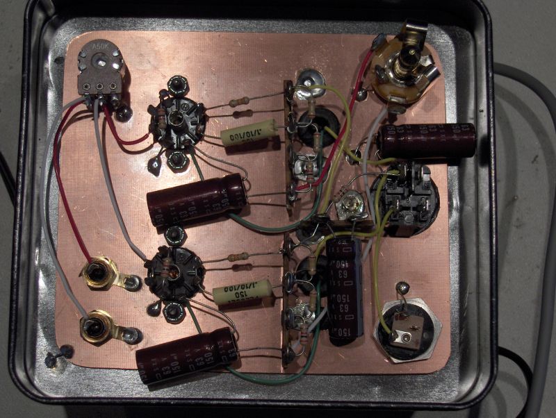
EDIT: Regardless as a beginner, you are better off looking at the circuit in some builds than trying to wire P2P from the schematic. Here's Pete's again:
starving_inside.jpg
 

Users who are viewing this thread

Back
Top