Quote:
No totally immune, just greatly reduced. It's a simulated free air measurement or "anechoic plate" that I'm using. In other words, the sound wave is not reflected between the surface (of dummy head) back to the inside of the cup. Instead it absorbed or passed through. I'm not giving away my secrets just yet. Only four people in the world (Tyll is one of them) have seen my setup.
Hi Marv, if you want to keep the sauce secret, you should stop using the word "anechoic" as it gives some serious hint

.
Quote:
He can use my data, but my current methods of data acquisition seem to provide rather murky CSD plots. Slowly but surely looking into it.
Arnaud has a little conversion routine for my spreadsheets Maybe he'll post a coupe here just for a look-see.
Purrin, I really admire the work you're doing dude. Lots of information in those plots. Thanks mang!
As Tyll mentioned, he graciously made some of his raw data available for me to extract CSD curves (see below). I have indeed created some macros in Excel to automate the data loading / reduction / and exporting of graphs. But as Tyll mentioned, there is potentially some issue with artificial dampening of the data and I hope Tyll will find some time to revisit this at some point (problem is that you'll need the headphones again to get some measurements done...).
What drove me to doing this work for Tyll was reading about headphone CSDs from this very thread and then helping Marv to create his CSD processing routine. While I think Marv is going truly an excellent work and really got his measurement skills well tuned, I also very much believe people need to be careful with interpreting Marv's results. In particular, most result published are so called "anechoic" plate (e.g. ~100% absorbing of incidence waves), which is nowhere near the actual operating conditions of the headphone. Marv has clearly expressed that he was trying to make driver related resonances standout rather than those acoustic resonances in the earcup cavity but lately this CSDs are trying to be interpreted as faithful renditions of the headphone ringing, which is not quite right.
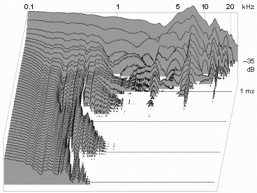
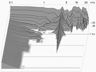
IMHO, every resonance (be it driver or acoustic one) should be looked at even though the CSD graphs can turn up ugly as a result. At the very least, Marv should post more of the following comparisons (http://www.head-fi.org/t/566929/headphone-csd-waterfall-plots/150#post_7767415 ):

Black: "Rigid Plate" Left Channel
Blue: "Rigid Plate" Right Channel
Yellow: "Anechoic Plate" Left Channel
Red: "Anechoic Plate" Right Channel
Quote:
Did I see a CSD plot for the SR-007 in this thread?
I thought I did, but then I used the "Search This Thread" tool on "007" and that didn't result in any SR-007 CSD plots.
Did the SR-007 get measured?
I loose track of what I post where and you also probably actually saw the results and then forgot the thread
. I posted some results here ( http://www.head-fi.org/t/572968/modeling-headphones-acoustic-performance#post_7774290 ) and here's the whole picture for the 007 vs. 009 comparison. Note that I am using InnerFidelity's background image because it is Tyll's data and he should be credited accordingly. But, just to keep it clear: this data was not officially acknowledged by Inner Fidelity and you will not find it on their website. It is just my shot at extracting CSDs from Tyll's data and although I could verify that the CSD for the whole impulse data matches the traditional FRFs from Tyll, I can't guarantee the results.
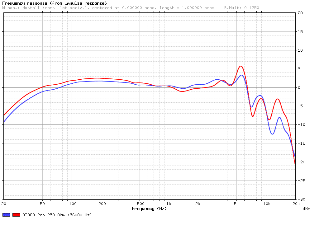
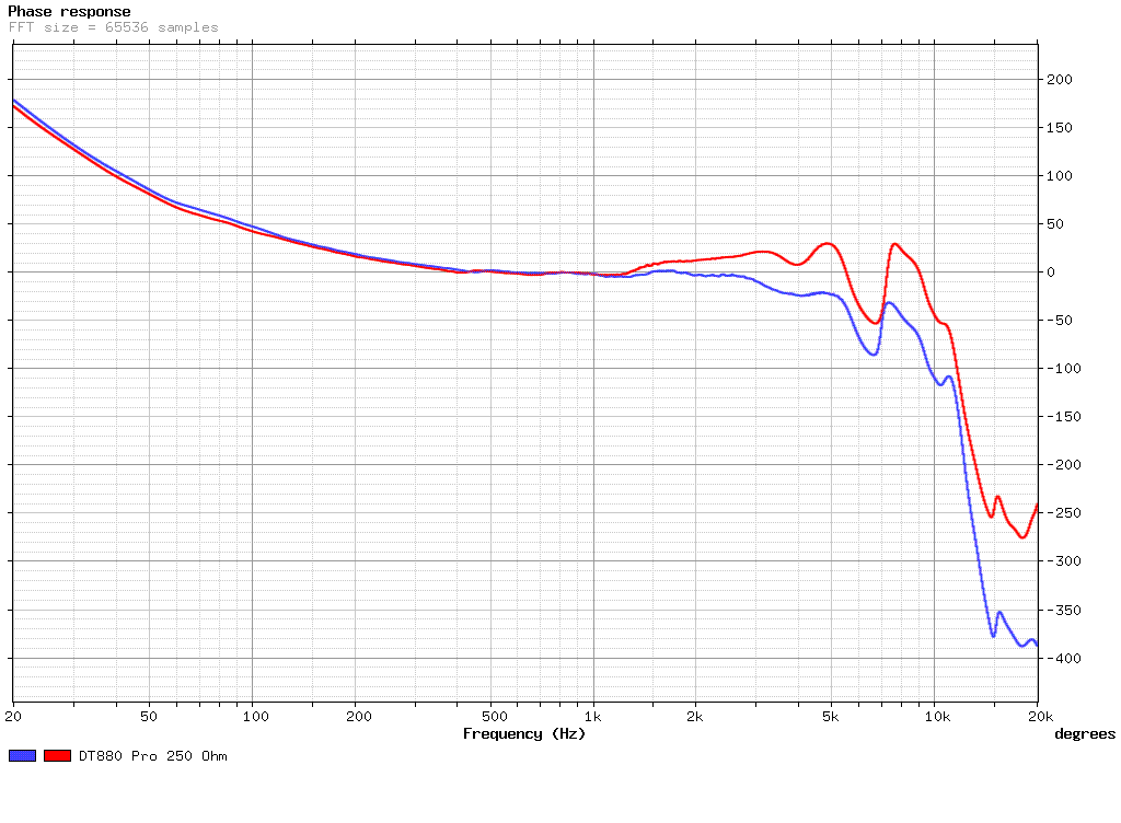
First a comparison of the classical magnitude response function to make sure my CSD post-processing in Excel was ok:

Next a comparison of SR007A and SR009 magnitude response functions (equalized for the dummy head response in typical listening environment, normalized by max SPL):

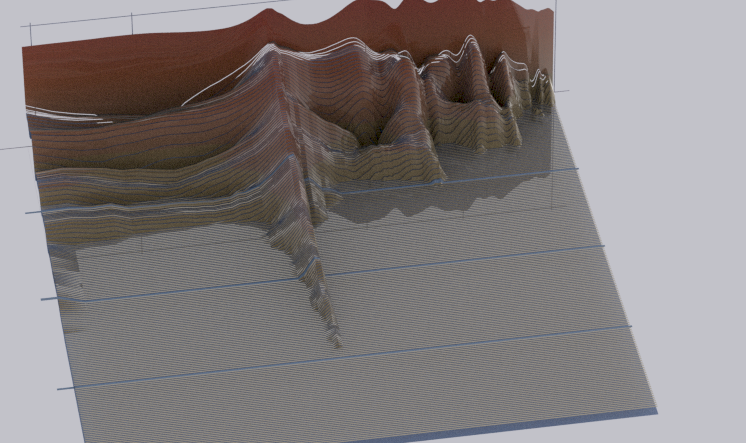
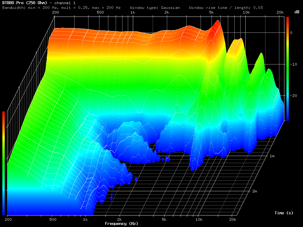
Finally, the CSDs extracted from the same (single position) impulse response data (equalized for the dummy head response in typical listening environment, normalized by max SPL):


")
