UPGRADING THE CRYSTAL (X0) ON ESSENCE STX
Jul 20, 2009 at 9:24 PM Post #61 of 246
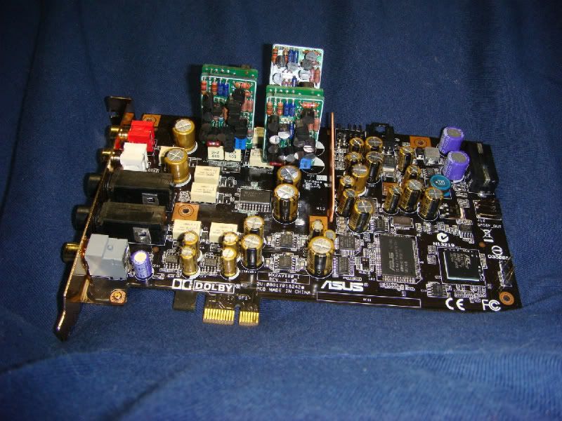
well, what the resolution of the stock clock on the STX?

there's a good tutorial to RMAA here : http://audio.rightmark.org/downloads...tGuide_V12.pdf

you need to reach as close to 0dB as possible in the pretest(w/o clipping!), and ideally if you can test both the lineout and HP out(in low/mid/high gain)....this would yield interesting data to compare against my ST measurements
smily_headphones1.gif
 
Jul 21, 2009 at 3:19 AM Post #63 of 246
From the pics on the second page, I see that you have to replace two of the pins and you have some hookup wire to attach it to the new clock. What about the wire/alligator clips? in the back of the module? Also how did you mount the thing on the Essence?

I'm very much interested in potentially doing this myself in the near future since I've gotten into DIY
smily_headphones1.gif
 
Jul 21, 2009 at 7:17 AM Post #64 of 246
Quote:

Originally Posted by taso89 /img/forum/go_quote.gif
From the pics on the second page, I see that you have to replace two of the pins and you have some hookup wire to attach it to the new clock. What about the wire/alligator clips? in the back of the module? Also how did you mount the thing on the Essence?

I'm very much interested in potentially doing this myself in the near future since I've gotten into DIY
smily_headphones1.gif


THIS ARE THE STEPS TO MAKE:
-first you unsolder the old crystal X1 from the board (two pins)
-then you mount the new modified crystal on the board.
-the signal or the output of new crystal whit 24,576Mhz you solder to the right unsoldered pin of the old crystal (pin46-input to av100) and the ground of the new one to the pin 39 on av100 or better for soldering to the near opamp that has the same ground.
-if you have all done, then just need to solder the power supply on the back of new crystal in my case it was 12V from computer PSU.
-Thats it!


If you want to do let me know I will send you maximized photos!
 
Jul 21, 2009 at 8:41 AM Post #66 of 246
why not installing a 1ppm clock instead of that 5ppm audio-gd stuff? several advantages :
-no need for a power supply(it will go the normal way through the SANYO caps, that will remove a lot of noise)
-better resolution(even if it loses 2ppm/year)
-just change it every year and you always get <5ppm...possibly on a removable adapter
 
Jul 21, 2009 at 10:09 AM Post #68 of 246
This audio-gd jz1 crystal solution is powered from DC 10-30V and has high fidelity filtering caps and transistors to filter far more noise out of the line as whit this two sanyo caps.. I think its an easy solution, you can also change it easy when you think the crystal has been older)
 
Jul 22, 2009 at 1:36 PM Post #69 of 246
good point!

anyway, that's your next upgrade : 8-pin DIP IC Socket

fotios did it : welcome to* The Electronic Audio Labs* web magazine

I've called a shop, they said they could do it...but only if the PCB doesn't have more than 2 layers! I will ask fotios

and anyway, he advised me to get rid of the holders, find the "perfect" op-amps and solder them directly on the PCB!
evil_smiley.gif
 
Jul 22, 2009 at 4:12 PM Post #70 of 246
Quote:

Originally Posted by leeperry /img/forum/go_quote.gif
good point!

anyway, that's your next upgrade : 8-pin DIP IC Socket

fotios did it : welcome to* The Electronic Audio Labs* web magazine

I've called a shop, they said they could do it...but only if the PCB doesn't have more than 2 layers! I will ask fotios

and anyway, he advised me to get rid of the holders, find the "perfect" op-amps and solder them directly on the PCB!
evil_smiley.gif


Changing out the DIP sockets is a good upgrade especially if your swapping opamps all the time. More of a mechanical upgrade though.
To make sure the contacts are nice and clean and quality.
You can get some nice opamps sockets gold plated..etc.

BTW, you really need to shrink down those pics they mak this thread way too wide!

I was looking at Zero profile sockets. They use the board it self as the socket although I am unsure if they are compatible with this design. The PCB has to be made to accept them I think. I haven't had time to read over the informaiton fully. They look like a product that may be of interest to audio DIY'ers.
 
Jul 23, 2009 at 2:35 PM Post #71 of 246
ok apparently they've shipped my 5 free samples :


I'll let you know when I have them
wink.gif


a friend of mine(who works as an electronician) told me that he could swap them for me
smily_headphones1.gif


all you need is a solder sucker and a very sharp soldering iron apparently : YouTube - Intalling Burson Opamp in less than 5 mins

I'm still undecided on whether I'll send back my ST card, I'll share a photo of the rusty stock DIP8 socket later today
smily_headphones1.gif


but fineart had a problem w/ the 1/4" HP plug that didn't hold his jacks, and mine has a rusty DIP8 socket...maybe Asus could improve QA
rolleyes.gif
 
Aug 1, 2009 at 6:10 PM Post #72 of 246
Hi GWorlDofSPACE, got inspired by your mods, and installed 3xBursons!
smily_headphones1.gif

but as you can see, I did it slightly different. I kept the sockets, and plugged in the Bursons, while aiming for the leads to be as short as possible. one of them had to be tilted a little. (see below)
top2.jpg

leftup.jpg


also the 2 caps beside I/V opamps had to be shifted..
back.jpg

to the back!


those HUGE mundorf's you've got there - what're their specs? Do you remember if they made a difference with the caps on, than without those on?

cheers mate, keep up the good stuff!
beerchug.gif
 
Aug 2, 2009 at 10:34 AM Post #73 of 246
Very impressive !!! Congratulations! This is also a very good solution to put the op-amps on the card.
I am using 1uf M-caps.
The sound whit the caps is more relaxed and neutral.
Please tell me your experience whit the 3B op-amps, how does it sound to you?
 

Users who are viewing this thread

Back
Top