I'm not very well versed in electronics, but after much digging... i know that DAC chips like Burr Brown PCM1794 and ESS Sabre outputs current signals. So it has to be converted to voltage signals.
The first stage "filter" is an I/V stage, which converts current signal to voltage signal. The 2nd stage "EQ" is a low pass filter stage.
I noticed this is quite a common circuit in many DACs that has current output. Some add a buffer or gain stage after this LPF (rare). I know what LPF does, but I don't know why it is needed after I/V stage... possible due to ultrasonic signals from the DAC and/or I/V stage?
Looking at opamp rolling threads, the Asus Xonar has a similar structure after the Burr Brown DAC chip and DIP8 sockets. Therefore, many have tried various opamps on I/V and LPF. If you could put in a adaptor socket, opamp rolling is possible. Imagine Sparkos Labs or Sonic Imagery discrete opamps in there, yummy!
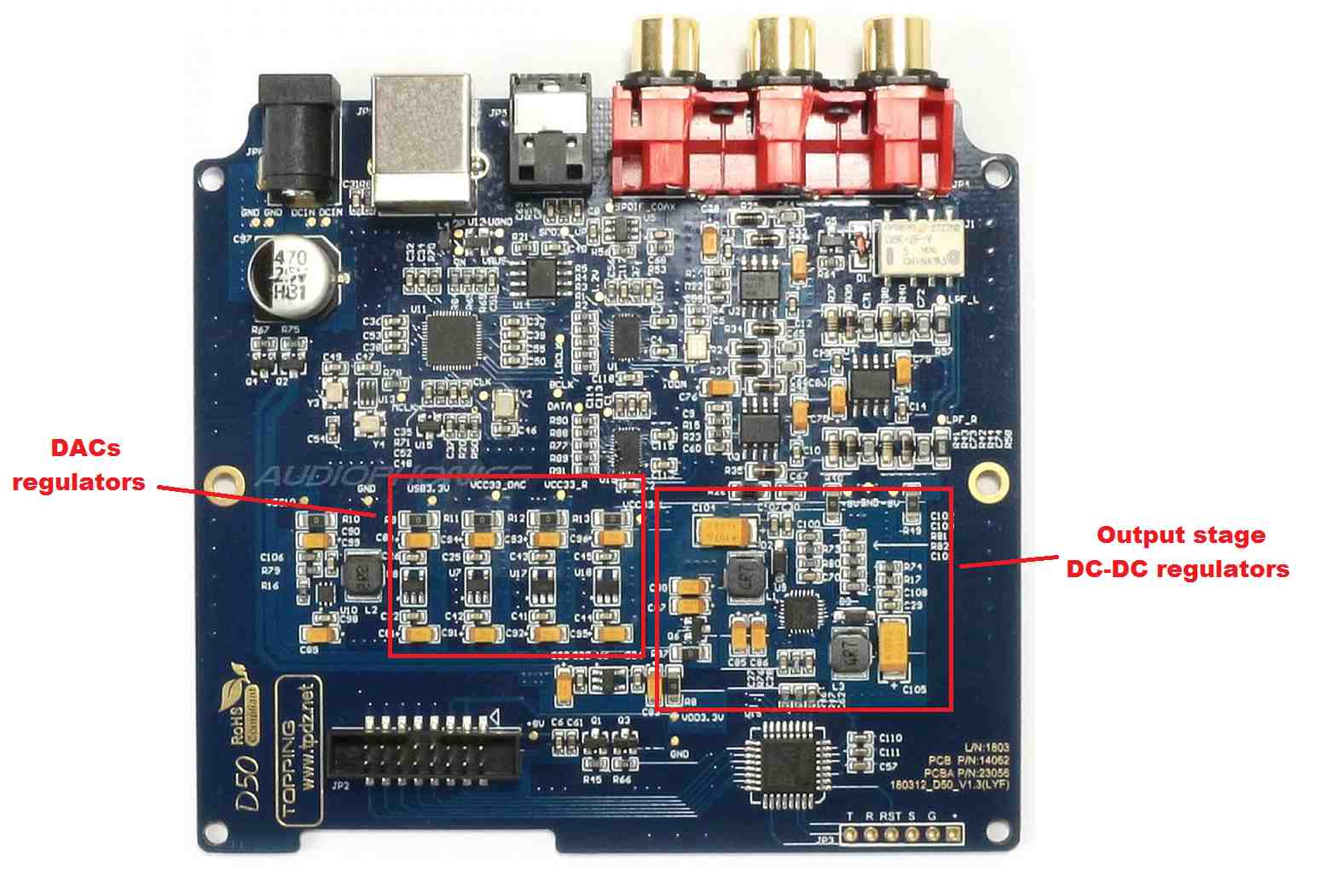
And if anyone is adventurous enough, you could DIY Salas's UltraBiB and Reflektor LPS (group buy in DIYaudio), and supply into individual circuits: USB receiver, SPDIF receiver, DAC chips, analogue stage (I/V & LPF).
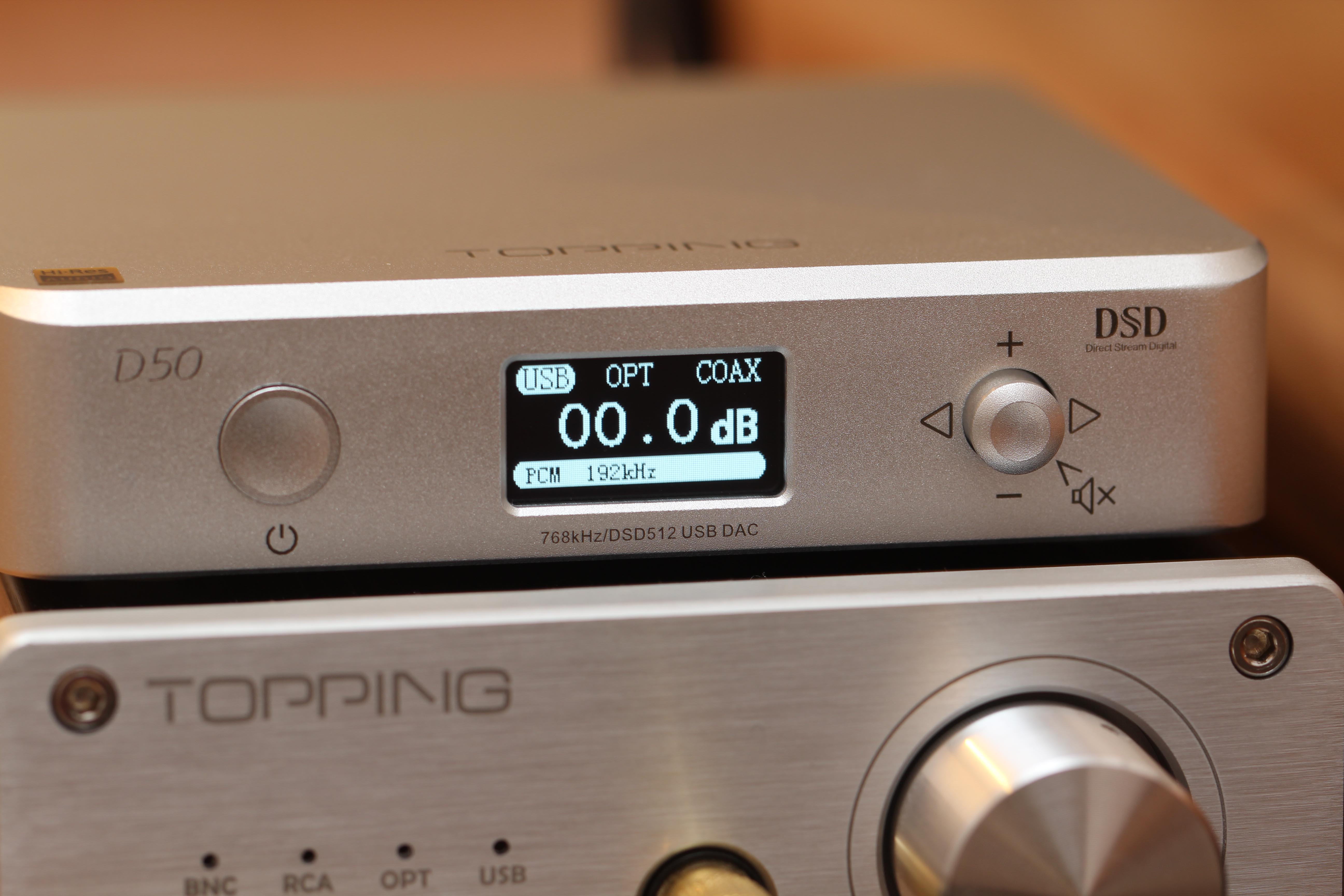
The D50 is so well laid out and labelled that it is possible to treat it as a DIY module and modify it to a person's heart's content. But it wouldn't fit that gorgeous CNC casings anymore.
I just bought another DAC: DAC DAC HS. Will compare it with D50 (using SPDIF input) over the next few weeks.
There is a thread on diyaudio.com for 9038Q2M dacs, its a bit hard to sift through to find the info you want (and can understand as a beginner, like myself) but it helps understand this particular DAC implemenation aswell as DACs in general, there are a few unsual things about it that helps to know for modding.
DAC chips usually have seperate ''voltage'' and ''current'' outputs. The voltage output would do I/V conversion of current output internally to simplify the external circuit, aimed at cheap and simple implentations. The current output allows the I/V conversion to be done externally, and with a well designed I/V stage has the potential to have lower distortion and better sound.
However, Sabre DAC chips combine the current and voltage outputs into one output, the DAC will only output true current if it sees a very low impedance load (basically 0).
The Sabre must use special I/V stage to achieve that, you can see it in the full circuit for D50's op amp stages a few posts after the one you quoted.
As I understand certain types of I/V stages wont work well with Sabre DACs because of it, like transformers, which have some impedance.
And there is actually low pass filtering happening in both of the op amp stages and is only a secondary function of each stage.
The first pair op amps main function is I/V conversion as you know.
The next op amps main function is converting the balanced signal to single ended, it combines the balanced signals from the DAC (positive and negative) and any difference between the signals is cancelled out, reducing distortion in the process.
For power supplies, having seperate transformers for the digital (USB, DAC) and analogue stages (DAC_L, DAC_R, output stage) would help get the most out of multiple supplies, it will provide isolation between the stages.
If you wanted to take it to absolute extreme you could use 3 seperate transformers, 1 for digital, 1 for left channel audio and 1 for right channel audio. the dimishing returns would be huge but thats how its done in some high-end DACs.


")
