I think im right but i just want to double check..
Im modding a 5.5g ipod but im not going to mod it to the line out. Im gonig to drill a hole in the back and run the wires straight through the caps and to the amp.
Anyway what i was wondering was where would be the best place to take the ground from? I was thinking of just using the existing ground in the normal headphone out (solder a wire inside the socket or something..) is there any reason why this wouldnt work?
Thanks for the help so far guys! Ive learnt so much from all of you in this thread.
Originally Posted by Ramblingman /img/forum/go_quote.gif I think im right but i just want to double check..
Im modding a 5.5g ipod but im not going to mod it to the line out. Im gonig to drill a hole in the back and run the wires straight through the caps and to the amp.
Anyway what i was wondering was where would be the best place to take the ground from? I was thinking of just using the existing ground in the normal headphone out (solder a wire inside the socket or something..) is there any reason why this wouldnt work?
Thanks for the help so far guys! Ive learnt so much from all of you in this thread.
I'm not positive on this, but just to be safe, take the output ground from the lineout ground (wherever you can trace it back to), but if by some chance the headphone ground is active, you don't want this! See if you can find a ground pin on the DAC chip and take the ground channel from there, the same as the signal to avoid any troubles.
Originally Posted by joneeboi /img/forum/go_quote.gif Hm, try to keep the battery as flush as possible. I'm struggling to imagine how the screen can mess up with the HD pushing against it. The PCB is big enough that it should disperse the pressure. Are your wires + hot glue + general tangle causing undue pressure on your screen?
Oh yes, and I forgot to mention, though I'm sure some have noticed by now. Happy 50,000th view! *party emoticon*
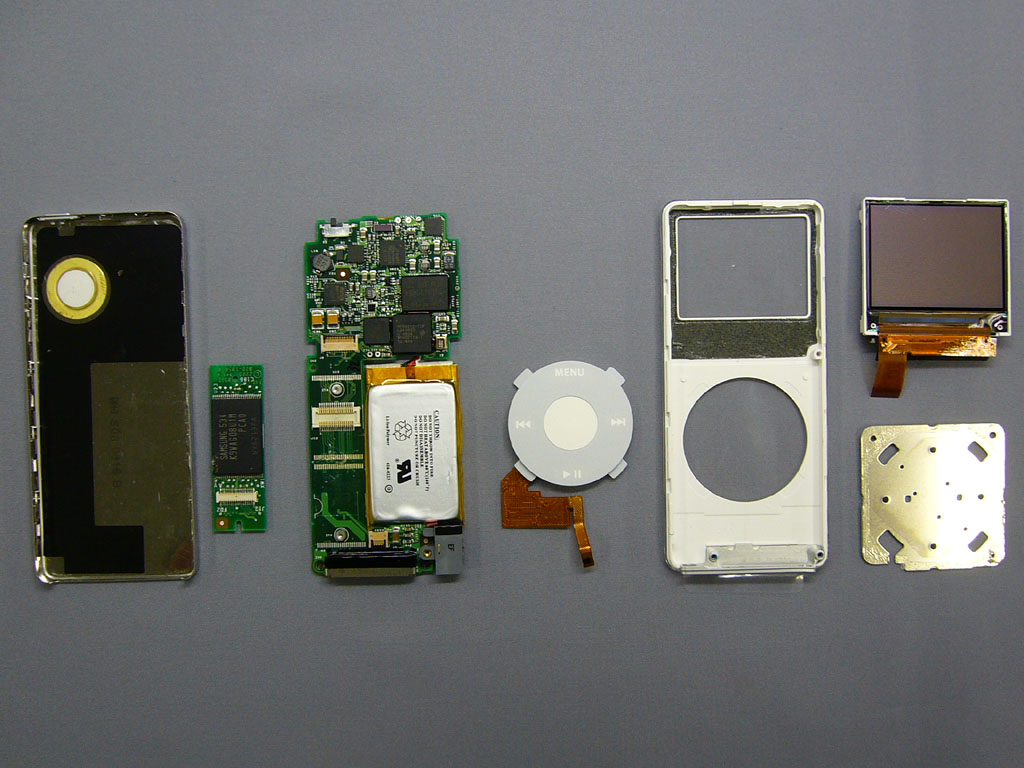
Originally Posted by joneeboi /img/forum/go_quote.gif I see what you're talking about. I think that those caps still might be for the dock because the coupling caps for the headphone jack should be on the headphone jack PCB. I can't say for sure for the photo, but at least in my 4G click wheel the coupling caps are on the HPJ PCB.
I've counted you on the OP too now, iQEM.
You should have mentioned you finished it. I remember seeing "diyMod nano (99% complete)" in your sig not too long ago, but now it's changed. And how come you don't buy a new iPod dock? By itself, it's very cheap, and shipping is very reasonable from Ridax in Sweden. I have an iPod FM transmitter and the dock could only be used for music and charging since they closed off the other pins. If you bought a new one, you could use it for whatever you wanted.
yup, i plan to order some dock on Qables...maybe less than dissassamble wallcharger all the time...lol still count for the shipping costs to indo though, i hope it's cheaper than normal...
note:
i used to buy parts/acessories from ebay but haven't try to buy things from Qables...
Quote:
Originally Posted by joneeboi /img/forum/go_quote.gif edit: I've linked a new CF to 1.8" adapter on the front page. It's probably a more reliable source, since my eBay CF adapter cost me 15 pounds (???). Also, I found a neat page with an iPod nano 1G dissection with very clear photos. It might be worth checking out. I discovered it while researching how to increase the nano's flash memory capacity.
interesting, but why only the white ipod nano 1stGEN that had a flash on seperated PCB, not on the logicboard itself ? strange...
And Fallen, I can't believe my 1000+ Member status is coming up. I haven't even prepared a speech yet!
Ramblingman:
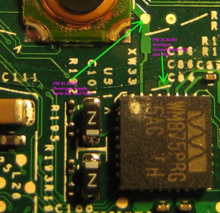
Check out the 5.5G's datasheet and look for pins 31 and 28. We don't exactly have a photo showing these pins, but I'm sure you can figure it out.
iQEM:
4GB nanos have the flash on a separate daughter card, like you see in the photo. I'm thinking you could take another 4GB flash, solder it onto the empty slot and try for an 8GB nano. Someone can try it.
Thanks for the link Joneeboi, that has been a great help and i think ive located the 2 pins you are talking about.
It looks like pin 28 just goes no where but i think ill be able to connect to the little silver circle that the green arrow is pointing to for pin 31. What do you reckon?
That's a great picture, Ramblingman. I think you could conceivably solder your wire to that circle. Just remember that the wires, solder and hot glue will all push up on the front panel so that the click wheel will cave in a little. Make sure your work is super clean and that you cut the signal to the headphone jack. Routing the wires around the metal frame to the back plate will also affect your fit. Think of where you want to drill the hole ahead of time so that you minimize wire travel. Think of how you're going to secure the wires both near the DAC and near the drilled hole. If you're using something really small, you may not have to worry as much. If not, you'll have to be more careful about these things. Let us know what your progress is like.
Ramblingman, that pin is too close to "next button". I think if you solder a wire there, the thickness of the wire will make a problem when pushing that button.
Thanks for the tips and concern guys, the wire im using is 30 AWG silver plated Kynar wire so its really thin and i think i might get away with connecting so close to the button. Ill test before i close it up completely.
Im just not sure where else i could hook up a ground?
Also where is the best place to disconnect the signal to the headphone jack? Wouldnt this be done when the "Z" caps or whatever they are are removed?
Ill hopefully get some time tonight to solder it up and ill post pics when i get it finished and together.
The caps im going to probably use are 5.6uF 250VDC Metallised Polypropylene caps but i also have some 22uF electrolytic caps to try but no black gates at the moment, they are taking their time to arrive!
Since you're not using the headphone jack for the line out, you won't need to cut its signal. There are some coupling caps right near the HPJ ribbon cable which would cut the signal if removed, but you don't need to do that.
Hi ntrl, welcome to head-fi. Sorry about your wallet.
I don't know of any cards not mixing well with the iPod 4Gs, but I have heard that A-Data works with the iPod minis. I don't know what the issue would be, but check out the thread, http://www.head-fi.org/forums/f15/my...d-mini-290743/. ruZZ.il had a Sandisk Extreme III that didn't work in his iPod mini 1G IIRC, but I haven't seen a compatibility chart laying out cards and iPod models anywhere.
edit: Never mind, it seems you've already checked that thread. In that case, I can't really help you. =I
This site uses cookies to help personalise content, tailor your experience and to keep you logged in if you register.
By continuing to use this site, you are consenting to our use of cookies.