The Apple diyMod: My Take on the Famous iMod [56k killer] Featuring 3G, 4G, 5G and nano 1G!
Feb 25, 2008 at 9:06 PM Post #946 of 3,220
Quote:

Originally Posted by BrinNutz /img/forum/go_quote.gif
But I do find it odd that the iPod still works with HP jack when those resistors are removed.


Yeah, those are the line out's filter resistors. The DAC has multiple outputs, so taking the signal from those resistor pads shouldn't affect the headphone signal.

Quote:

Originally Posted by BrinNutz /img/forum/go_quote.gif
The other set of resistors must be for the HP jack methinks?


Which ones were you talking about?
 
Feb 26, 2008 at 5:53 AM Post #947 of 3,220
dscf4104copycr0.jpg


See the pair under where I took the set off already? I think those might be for the HP jack no?
 
Feb 26, 2008 at 7:56 AM Post #948 of 3,220
Quote:

Originally Posted by joneeboi /img/forum/go_quote.gif
Count it! Kudos, Ron. That indeed was quick. And don't worry about iQEM, he's been doing his diyMod for months now.
tongue.gif
(I believe in you, iQEM)


Thanks ruZZ.il & jon...
biggrin.gif


Actually iQEM has done the internal wiring of his iPod. His LOD is the only problem. We both use the same dock connector. It's hard to built because actually it's a charger for iPod (4 pins only), modified to act as line-out dock connector. The pins is so tiny and fragile, bend it too much and it will break.

iQEM already test his iPod diyMod with ALO's iMod dock connector, it worked.
 
Feb 26, 2008 at 8:24 AM Post #949 of 3,220
Quote:

Originally Posted by joneeboi /img/forum/go_quote.gif
Count it! Kudos, Ron. That indeed was quick. And don't worry about iQEM, he's been doing his diyMod for months now.
tongue.gif
(I believe in you, iQEM)


yeah, my mod work though...last week i had a chance to compare it to Gmod (my friend owned it) using ALO supercotton to Corda2MOVE + same cans...me & him pretty sure that the different's there (separation & bass) but the diff come from my nano 1st GEN 2gb, that only use 192kbps source (the real Gmod using lossless)...
biggrin.gif
hooray !!!
 
Feb 26, 2008 at 8:26 AM Post #950 of 3,220
Quote:

Originally Posted by Ron.id /img/forum/go_quote.gif
Thanks ruZZ.il & jon...
biggrin.gif


Actually iQEM has done the internal wiring of his iPod. His LOD is the only problem. We both use the same dock connector. It's hard to built because actually it's a charger for iPod (4 pins only), modified to act as line-out dock connector. The pins is so tiny and fragile, bend it too much and it will break.

iQEM already test his iPod diyMod with ALO's iMod dock connector, it worked.


yup...that's what i've talked about, it's not an regular ALO lod to mini...it's an ALO supercotton...yay !
biggrin.gif
 
Feb 26, 2008 at 3:43 PM Post #951 of 3,220
Quote:

Originally Posted by BrinNutz /img/forum/go_quote.gif
See the pair under where I took the set off already? I think those might be for the HP jack no?


I see what you're talking about. I think that those caps still might be for the dock because the coupling caps for the headphone jack should be on the headphone jack PCB. I can't say for sure for the photo, but at least in my 4G click wheel the coupling caps are on the HPJ PCB.

I've counted you on the OP too now, iQEM.
smily_headphones1.gif
You should have mentioned you finished it. I remember seeing "diyMod nano (99% complete)" in your sig not too long ago, but now it's changed. And how come you don't buy a new iPod dock? By itself, it's very cheap, and shipping is very reasonable from Ridax in Sweden. I have an iPod FM transmitter and the dock could only be used for music and charging since they closed off the other pins. If you bought a new one, you could use it for whatever you wanted.

edit: I've linked a new CF to 1.8" adapter on the front page. It's probably a more reliable source, since my eBay CF adapter cost me 15 pounds (???). Also, I found a neat page with an iPod nano 1G dissection with very clear photos. It might be worth checking out. I discovered it while researching how to increase the nano's flash memory capacity.
 
Feb 26, 2008 at 9:21 PM Post #952 of 3,220
Got my wire today from John's shop on eBay!

WTH am I going to do with this much, I just needed a couple feet lol

I need to find somewhere local for fine tip and find solder, unless someone has some extras I can have?
 
Feb 26, 2008 at 10:13 PM Post #953 of 3,220
There are 3 Radio Shacks in your lovely city. You should be able to find what you need there, along with different gauge/colour hookup wiring if you didn't like the navships stuff. Pick up some KSC75s while you're there.
tongue.gif
Sorry, when Radio Shack went out of business not much more than a year ago, I stocked up on like, 7 KSC75s which have all somehow disappeared. They were going for $10 a pop. It'll probably be a bit more expensive there. But anywho, you should be able to find whatever you need at RS. Costs a couple bucks, most likely.
 
Feb 27, 2008 at 4:14 AM Post #954 of 3,220
Rock on jon, I'll hopefully check tomorrow!


I am having a problem now putting the case back together with the new battery and HD in (worked fine with old battery) where the screen works when not in compressed area, but when I put pressure to push the case together, the screen lights up but has no text, a reset does it fine after pulling it apart though.
 
Feb 27, 2008 at 4:45 AM Post #955 of 3,220
Hm, try to keep the battery as flush as possible. I'm struggling to imagine how the screen can mess up with the HD pushing against it. The PCB is big enough that it should disperse the pressure. Are your wires + hot glue + general tangle causing undue pressure on your screen?

Oh yes, and I forgot to mention, though I'm sure some have noticed by now. Happy 50,000th view! *party emoticon*
 
Feb 27, 2008 at 6:51 AM Post #956 of 3,220
when making the dock,

since the blackgates can be in series with the signal, can I just solder both pins of the blackgates + the wire to the connector pins?


so basically three parts to the one pin?

thanks
 
Feb 27, 2008 at 7:14 AM Post #957 of 3,220
Quote:

Originally Posted by fatman711 /img/forum/go_quote.gif
when making the dock,

since the blackgates can be in series with the signal, can I just solder both pins of the blackgates + the wire to the connector pins?


so basically three parts to the one pin?

thanks


Huh?

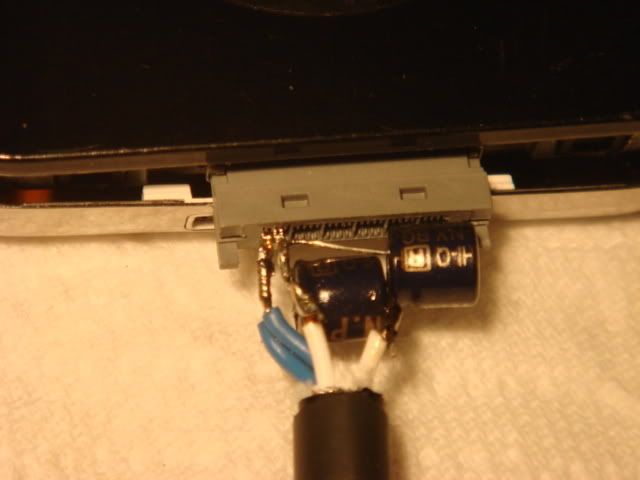
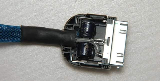
The blackgates are in series with the signal (pins 3 and 4). You solder the caps to each of those pins with wires going to to the other legs on the caps and another wine going to pins 1 and 2 for ground.
 
Feb 27, 2008 at 8:23 AM Post #958 of 3,220
It's not too clear in the image, but I think you can gather from what's there and the information FallenAngel just dropped.

Pins 1 and 2: Go straight to ground
Pin 3: Pin to one BG leg, other BG leg to right channel wire
Pin 4: Pin to one BG leg (different BG), other BG leg to left channel wire

wgr73
diymod5gwgr73.jpg


ruZZ.il (he used different pins)
dsc0185zs8.jpg
 
Feb 27, 2008 at 8:37 AM Post #959 of 3,220
correct me if I'm wrong, but If I want to do a 4 wire braid, 2 ground, 1R and 1L, I can use pins 1 and 2 for ground right?

thanks a lot for the replies
 
Feb 27, 2008 at 8:44 AM Post #960 of 3,220
Quote:

Originally Posted by fatman711 /img/forum/go_quote.gif
correct me if I'm wrong, but If I want to do a 4 wire braid, 2 ground, 1R and 1L, I can use pins 1 and 2 for ground right?

thanks a lot for the replies


Yep. Use either one or both of those pins, they're connected on the iPod PCB anyway.

joneeboi - damn buddy, you always have fantastic details in your answers, I always just leave little notes
smily_headphones1.gif
And hey, 6 more posts before 1000
tongue.gif
 

Users who are viewing this thread

Back
Top