Speaker amps for headphones
Oct 6, 2013 at 12:07 PM Post #1,186 of 3,873
Ahhhhh, yes!
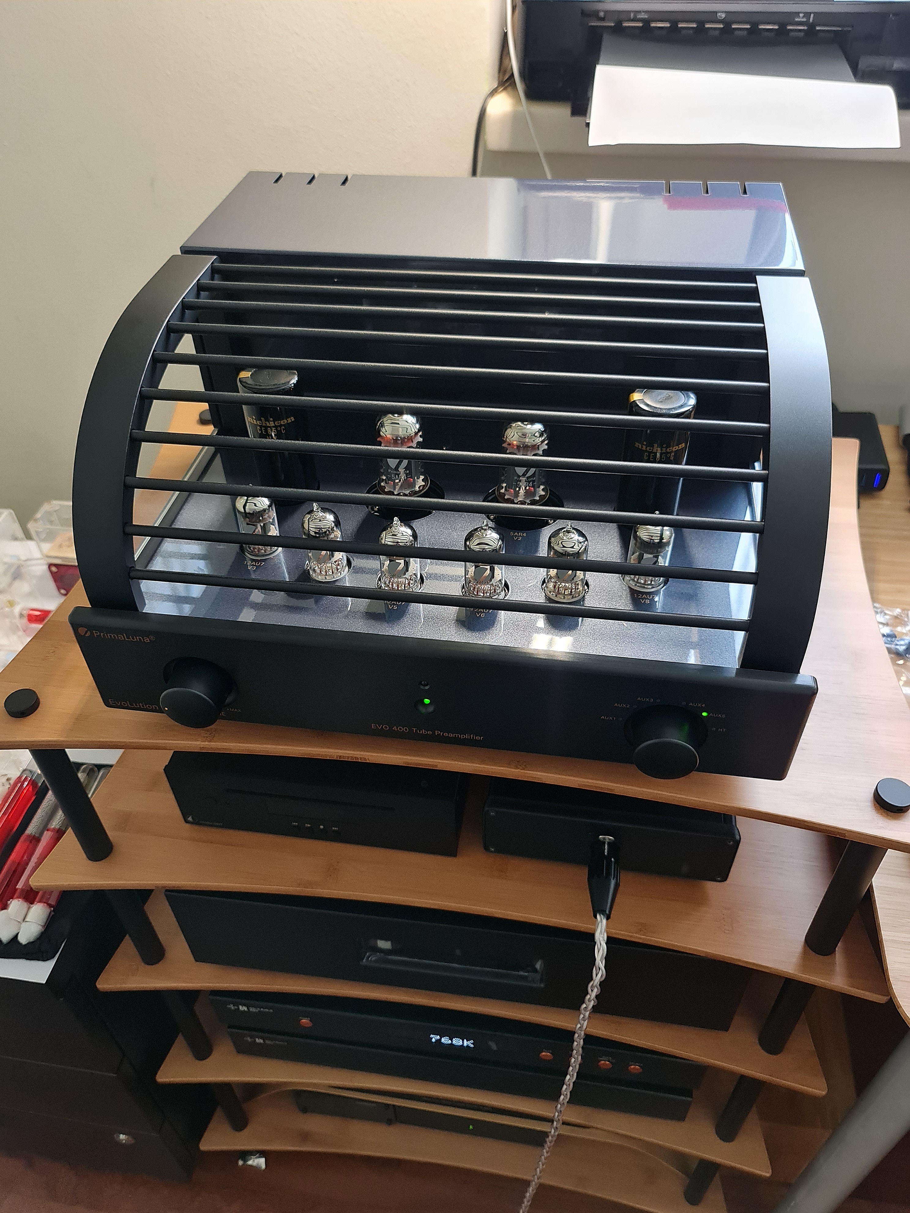
The "burn marks" or "smoke" I thought I saw are actually shadows from the backlighting!
redface.gif


Very cool, enjoy!
biggrin.gif

 
Hehe no prob. You had me scouring the board for issues though LMAO. 
biggrin.gif

 
Oct 21, 2013 at 7:32 PM Post #1,187 of 3,873
Let's get this thread kicked off again! Mike, how did your toy robot project come out? Did you learn a bunch of stuff? After much delay with some parts of my F5, they have finally arrived and will hopefully be finishing up tonight or tomorrow. I can't wait!
 
Quote:
Yeah, nice job, Brunk! I am amazed at how few through-hole components it seems you had to solder, just going by the photos you've provided. It suddenly doesn't look all that intimidating to me. (Last words...)

I've got about half as much soldering to do with this toy robot I've ordered as my first PCB soldering effort... :wink:


http://www.amazon.com/gp/product/B002VKZBMY


Mike

 
Oct 21, 2013 at 7:45 PM Post #1,188 of 3,873
I haven't started yet!   


Actually, I am still intimidated (chicken), but I've been waiting for about a 6-hour block of free time, some Saturday morning, so that I can make a lot of progress in one sitting.  I don't have a place where I can leave it all setup, so dragging it all out and putting it away for multiple 30-minute sessions is not appealing.   (Hint:  I wish I had a barn-sized man-cave to call my own.)
 
Mike
 
Oct 21, 2013 at 7:52 PM Post #1,189 of 3,873
  I haven't started yet!   
 
 
Actually, I am still intimidated (chicken), but I've been waiting for about a 6-hour block of free time, some Saturday morning, so that I can make a lot of progress in one sitting.  I don't have a place where I can leave it all setup, so dragging it all out and putting it away for multiple 30-minute sessions is not appealing.   (Hint:  I wish I had a barn-sized man-cave to call my own.)
 
Mike

Hah! I have a funny habit of delaying too, even after parts have finally arrived! Like you stated, I think it's the fact of finding the time block and motivation to get it done, almost like a student cramming intensely for exams lol. Yeah it can be difficult to find an adequate space to be able to leave the stuff hanging about. To help alleviate some of that, I like to keep projects in their own boxes, and tools in another box. It makes lugging out the stuff needed much more efficient, less confusing, and can be stowed away in a closet somewhere.
 
Looking forward to your results when you decide to BBQ that chicken Mike!
 
Oct 21, 2013 at 11:56 PM Post #1,190 of 3,873
Mom liked to do puzzles. She couldn't leave them out so she had me put up a couple brackets extending a couple feet off the wall over the door to the plant room. She would then put her work on a piece of plywood. When she was done with a session, she'd slide the plywood on the brackets. It would keep the kids out of it and was easy to retrieve. She slept very infrequently and you'd see her working her puzzles all hours of the night.
 
Oct 22, 2013 at 1:52 AM Post #1,193 of 3,873
   
That sounds like it's right on the edge of getting a decent matched set. The major problem is that it's not like a standard fixed resistor, the values are highly non-linear as you attenuate the signal. Good luck!

Well, through the magic of science, I was able to get 10 pairs of matched LDR's.  With the worst matched pairs (worst shunt with worst series LDR) I should have no more than 3 dB channel imbalance right at maximum attenuation (-60 dB or better). That's using a 500k ohm dual log pot to drive the LEDs for better attenuation.  The 100K ohm that George recommends only yields about -40 dB on this set of LDRs.  Going to 500k will allow better than -60 dB at minimum volume.  Of course, that will make balancing more of a challenge.
 
I grabbed a set with about 1 dB channel imbalance at the worst point and built it up.  I'm using the 100k log pot now.  Not real happy with only 40 dB signal range, so I'll wait for the next Mouser order to arrive (Wednesday, fingers crossed) and drop in the 500k ohm.  With some series correcting impedance I should be able to keep this set to ~1.2 dB channel imbalance at the worst point with the larger control pot. 
Once I get the control pot worked out, I'm going to install it in my Carver M-200T (which now has a 4 pin XLR on the front panel tied to the speaker taps).
 
Not bad for the first time out of the gate.  Comparing it to a First Watt B1 pre, I can't convince myself I hear any differences.  Too much time between cable swaps...  Which leads me to my next project, a proper A/B box!
 
Oct 22, 2013 at 10:04 AM Post #1,195 of 3,873
  Well, through the magic of science, I was able to get 10 pairs of matched LDR's.  With the worst matched pairs (worst shunt with worst series LDR) I should have no more than 3 dB channel imbalance right at maximum attenuation (-60 dB or better). That's using a 500k ohm dual log pot to drive the LEDs for better attenuation.  The 100K ohm that George recommends only yields about -40 dB on this set of LDRs.  Going to 500k will allow better than -60 dB at minimum volume.  Of course, that will make balancing more of a challenge.
 
I grabbed a set with about 1 dB channel imbalance at the worst point and built it up.  I'm using the 100k log pot now.  Not real happy with only 40 dB signal range, so I'll wait for the next Mouser order to arrive (Wednesday, fingers crossed) and drop in the 500k ohm.  With some series correcting impedance I should be able to keep this set to ~1.2 dB channel imbalance at the worst point with the larger control pot. 
Once I get the control pot worked out, I'm going to install it in my Carver M-200T (which now has a 4 pin XLR on the front panel tied to the speaker taps).
 
Not bad for the first time out of the gate.  Comparing it to a First Watt B1 pre, I can't convince myself I hear any differences.  Too much time between cable swaps...  Which leads me to my next project, a proper A/B box!

 
Oh great for you! Hopefully you won't find the channel imbalance audible at louder listening levels. I'm not surprised you're having difficult time discerning the differences between the two. I use an A/B box from MCM electronics that is quite inexpensive. I know it's not a DIY product, but you can always put better cabling in it hehe. The form factor is really convenient. Give it time and I'm willing to bet you'll hear low level signals you haven't heard before.
  Gee Brunk, it's obvious from reading your post that there's a lot more to building a great amp (even from a kit) than knowing how to solder.  
 
I suspect I'll be sticking to toy robots and soldering power cables.
 
biggrin.gif

Yeah there certainly is. The main issue with the F5 is finding parts that aren't available anymore if you really want the best quality FETs. Then there happens to be things that aren't listed on the BOM, resistor values you need to figure out yourself, parts you may have ordered that don't fit, upgrades, drilling etc.
 
Don't be discouraged though, it is frustrating, but it's part of the challenge that makes us savor the finished result even more. I have learned a great deal building this amp, that alone is priceless.
 
Oct 22, 2013 at 10:21 AM Post #1,196 of 3,873
Oh, the joy and self-satisfaction of craftsmanship!
 
I envy you the experience of knowing you are listening to a great amp, built with your own hands and a considerable measure of decision-making, troubleshooting, and frankly, a tenacious passion that most people lack.
 
It brings tears to my eyes, seriously.  People just don't know how to work with their hands these days. You are perpetuating a dying art.
 
It's your raw passion that I most admire.  Keep that fire burning!
 
beerchug.gif
  
 
Mike
 
Oct 22, 2013 at 10:51 AM Post #1,197 of 3,873
  Oh, the joy and self-satisfaction of craftsmanship!
 
I envy you the experience of knowing you are listening to a great amp, built with your own hands and a considerable measure of decision-making, troubleshooting, and frankly, a tenacious passion that most people lack.
 
It brings tears to my eyes, seriously.  People just don't know how to work with their hands these days. You are perpetuating a dying art.
 
It's your raw passion that I most admire.  Keep that fire burning!
 
beerchug.gif
  
 
Mike

Thanks Mike! I really appreciate your kind words. I hope to enlist more in the ranks of DIY, it keeps us consumers educated, and manufacturers honest on their toes. Win-Win for everybody.
beerchug.gif

 
Oct 22, 2013 at 2:45 PM Post #1,198 of 3,873
  By the way, I received a Resonessence Concero USB DAC today - Sheesh!  It sure sounds great with the MG3!
 
More later when I've put some hours on it...
 
Mike

 
For future DAC shoppers (Gary?) here are my first impressions of the Resonessence Concero with MG3:   
 
http://www.head-fi.org/t/634760/resonessence-labs-concero-discussion-review-thead/1230#post_9911813
 
Oct 22, 2013 at 7:28 PM Post #1,199 of 3,873
This is OT, but I had to share it here as I started fantasizing about it with the HE-6 LMAO. Do you like "Electronica"? 
eek.gif


Oct 22, 2013 at 10:38 PM Post #1,200 of 3,873
   
Oh great for you! Hopefully you won't find the channel imbalance audible at louder listening levels. I'm not surprised you're having difficult time discerning the differences between the two. I use an A/B box from MCM electronics that is quite inexpensive. I know it's not a DIY product, but you can always put better cabling in it hehe. The form factor is really convenient. Give it time and I'm willing to bet you'll hear low level signals you haven't heard before.
Yeah there certainly is. The main issue with the F5 is finding parts that aren't available anymore if you really want the best quality FETs. Then there happens to be things that aren't listed on the BOM, resistor values you need to figure out yourself, parts you may have ordered that don't fit, upgrades, drilling etc.
 
...snip...

Actually, at louder listening levels, the channel balance is very close, owing to the way I matched the LDR's.
 
That A/B box you linked looks very intriguing.  Already have parts on order, though.  DIY projects are always a challenge.  Part art, part science.  I've got F2 and F2J schematics sitting on the desk waiting to be the next project.  It won't have the voltage swing for the HE-6, but it will be fine for more efficient orthos and it will be my first DIY amplifier, so it will be good learning/proving ground.
 
Thanks for the inspiration, brunk!  
 

Users who are viewing this thread

Back
Top