


gazzington
Headphoneus Supremus
I've updated my wm1a to the new firmware. Yeap less bass but bigger soundstage. Use the eq a bit and you have more bass and large soundstage. Win win
I like Tin Pan Alley. How did 3.02 change?Just listening to Stevie Ray Vaughan (Tin Pan Alley) with the new 3.02 firmware and I really like it so much more than the 3.01.
Even my Shure SE846 makes the music shine! Tomorrow I try the Solaris! I wanted to sell the WM1Z to buy a SP1000/2000 but doubting very much right now.
You can always try it and then just go back the previous one if you don't like it or raise the subbass in EQ. I guess these observations are all with EQ off. I pressume sony just tweak the EQ behind the scenes and then present it flat in GUI. I discovered this when I extracted and unscrambled the Xuelin ihifi 990 firmware. I could tweak default bassline EQ.
BTW where can I get copies of old firmware from to experiment?
What is this black magic? Please tell me more
What is this black magic? Please tell me more
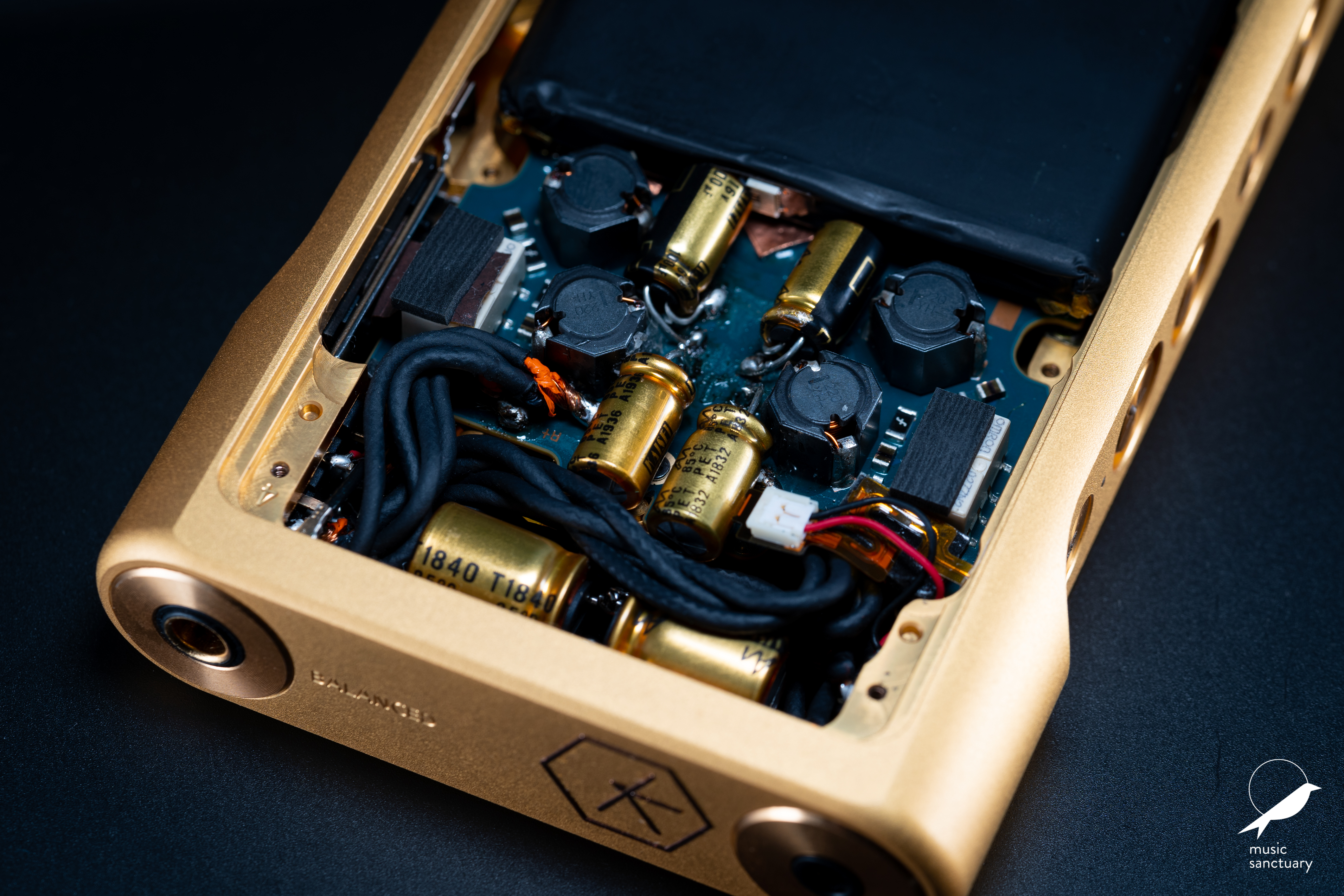
Basically removing the faulty WM-PORT Securing in its place a USB-C and soldering the USB power and data lines to the corresponding pins.
Thanks mate. That's awesome. It'll be good to keep a copy of back catalogue firmwareGo a few pages back and I posted the link to my DropBox where all fw, usb driver, manuals and RockBox tool resides. Windows only
Good question! I would like to know more! The WM port and Type C have very different physiques ?Are the pin outs so identical that that would be possible ?
Good question! I would like to know more! The WM port and Type C have very different physiques ?
Good question! I would like to know more! The WM port and Type C have very different physiques ?

I'm trying to get an idea of how the update impacts the 1Z /MDR-Z1R combos sound. Anyone with this combo do the update yet. Redcarmoose? Anyone?
I never realized that the USB C connector has 24 pins! I had assumed it was similar to USB 2, which only has 4 pins.
So I guess you could connect the Vbus power and Grd pins, and a Data pin pair, and connect power to the Detect pin. Looks like it should be possible, as the WMPort cable USB end only uses 4 leads, so that is all you you have to work with, and don't need to worry about the other pins which are used for audio, digital, etc, which is only on the cradle.
https://en.wikipedia.org/wiki/USB-C
USB-C receptacle A pin layout
Pin Name Description
A1 GND Ground return
A2 SSTXp1 SuperSpeed differential pair #1, TX, positive
A3 SSTXn1 SuperSpeed differential pair #1, TX, negative
A4 VBUS Bus power
A5 CC1 Configuration channel
A6 Dp1 USB 2.0 differential pair, position 1, positive
A7 Dn1 USB 2.0 differential pair, position 1, negative
A8 SBU1 Sideband use (SBU)
A9 VBUS Bus power
A10 SSRXn2 SuperSpeed differential pair #4, RX, negative
A11 SSRXp2 SuperSpeed differential pair #4, RX, positive
A12 GND Ground return
USB-C receptacle B pin layout
Pin Name Description
B12 GND Ground return
B11 SSRXp1 SuperSpeed differential pair #2, RX, positive
B10 SSRXn1 SuperSpeed differential pair #2, RX, negative
B9 VBUS Bus power
B8 SBU2 Sideband use (SBU)
B7 Dn2 USB 2.0 differential pair, position 2, negative[a]
B6 Dp2 USB 2.0 differential pair, position 2, positive[a]
B5 CC2 Configuration channel
B4 VBUS Bus power
B3 SSTXn2 SuperSpeed differential pair #3, TX, negative
B2 SSTXp2 SuperSpeed differential pair #3, TX, positive
B1 GND Ground return
***********************************************************************************
https://www.rockbox.org/wiki/SonyWMPort
Overview
This page documents what is known about the Sony WM-Port. It appears that this port could have two versions: 1.0 and 2.0 but the difference is probably only in software or marketing.
Electrical
Pinout
The WM-Port uses a 22-pin connector. It uses the following layout:
Pin Direction Name Meaning
1 GND Ground
2 RESERVED (OTG)
3 D+ USB Data
4 D- USB Data
5 GND USB Ground
6 RESERVED
7 IN VIN Vin (5V)
8 IN RXD/WAKE RxD/Wake
9 IN CRD_AD Cradle Detect
10 OUT TXD/SLEEP TxD/Sleep
11 IN USB_DET USB Detect (VBUS)
12 OUT UNREG_OUT Battery (VBAT)
13 IN AU_L_IN Left Audio In
14 OUT AU_L_OUT Left Audio Out
15 AU_COM Audio Ground
16 IN AU_R_IN Right Audio In
17 OUT AU_R_OUT Right Audio Out
18 VIDEO-GND/GND Video Ground
19 VIDEO-IN/OUT/OPEN Video In/Out
20 IN DCIN DC Detect (VDCIN)
21 OUT DIGITAL_OUT/OPEN Digital Audio Out
22 GND Ground
Power
Pin 7 is always powered with the available voltage. Pin 20 and 11 can be used to distinguish between DC and USB as follows:
- connected to USB: pin 7 and 11 powered
- connected to DC: pin 7 and 20 powered
instructable. Depending on the values, recording and/or line-out might be available and the volume might be fixed or variable:
Resistor Recording Line-Out Volume Comment
inf No No USB Cable
220k Yes No ?
100k Yes Yes Variable
68k Yes No ?
47k No Yes Fixed
33k No Yes Variable
22k Yes Yes Fixed
15k Yes Yes Variable
10k No Yes Variable
4.7k No Yes Fixed
[paste:font size="5"]Control
The control is made by UART over RxD and TxD.

