Since
@atomicbob has posted his full Schiit Audio Yggdrasil 2 measurements here, I'm copying (below) the Yggdrasil 2 measurements post I made in the original
Schiit Yggdrasil Impressions thread.
Since
@amirm on reddit said (in err) I only measured the balanced outputs (when I think he knows very well I included measurements from
both unbalanced and balanced outputs for frequency response, THD+N, and linearity), I've added additional emphasis to make even clearer which outputs each of the measurements below is from.
NOTE 2018-06-15: Revised Yggdrasil 2 linearity measurements posted (click).
I attended the talk. It was mostly about knowing which FFT parameters to use and making sure you are using bit-exact path to test products. My team wrote the Windows audio stack while I was at Microsoft, and one of my professional specialities is signal processing (I managed that team at Microsoft too) so, neither was news to me. His testing and mine both use bit-exact and I have taken his measurements and replicated them on my Audio Precision analyzer showing the same problems. In almost all cases Bob's data actually matches mine. It is just that his words are far more positive and people go by that, instead of data that represents otherwise.
I have shown this numerous times on ASR Forum. There is no question that Schiit DACs don't measure well no matter who measures them. Buy them for other reasons than engineering excellence.
Yeh but give me credit for having more Audio Precision gear than anyone!

There are no less than three of them in this picture (with one just peeking from the corner):
Seriously, you are right that it is easy to make mistakes and knowledge level it takes to test mixed-signal products like DACs can be pretty large. I like to think that as an owner of such measurement gear for 20+ years, and professional experience related to everything here from analog to digital and signal processing, I know what I am doing. But if I am not, I am open to others showing otherwise. So far, that has not happened.
So while there can be doubt in everything, I suggest by default you should accept the data as presented unless it is shown otherwise. Doing it in reverse means closing one's eyes to information that is purely created to make consumers more informed.
@amirm, it seems to me you have a personal agenda with regard to Schiit Audio. Some points:
- Schiit Audio has been very forthcoming about the fact that their multi-bit DACs will in general not measure as well as delta-sigma DACs (theirs or others). They've been very upfront about this, and have repeatedly stated that they simply feel their multi-bit DACs sound better, and a lot of their customers agree. I have purchased most of their multibit models, understanding they won't measure as well as their delta-sigma counterparts, just as I also know a simple CMOY portable amp probably will measure better than all of my favorite tube amps.
- The sensationalism of your posts appears to be clearly intended to have your readers believe that you somehow found them out in an "ah-ha!-look-what-i-found-guys!" manner. Yet they've been quite frank about this discussion since the first version of the Yggdrasil was released (and with every multi-bit DAC they've released since).
- You seem dead set on interpreting the results (especially where Schiit's concerned) in a manner that is consistent with what I (again) feel is clearly a personal agenda or bias with regard to Schiit Audio. And your interpretation of the linearity error plot -- using your +/-0.1 dB threshold -- is one I have not specifically seen anywhere. I'm not saying nobody else is using it, only that I've not seen it used elsewhere. I am genuinely wondering where this standard originated -- I'm assuming that the +/-0.1 dB threshold on that type of measurement references a specific standard, so I'm wondering where I can read more about it.
- When it comes to similar tests conducted elsewhere, it seems the narrative can be quite different. Let's look at John Atkinson's measurement of another multi-bit DAC (the HoloAudio Spring DAC "Kitsuné Tuned Edition" Level 3), starting with this plot in it (below):
- John said (about the above plot):
A relevant issue with resistor-ladder DACs is the linearity error: Will a digital signal at, for example, –80dBFS be reproduced at the outputs by an analog signal the same 80dB down from full level? However, the Spring performed well in this respect (fig.8). When I examined linearity, the error was negligible down to –60dBFS, and remained below 1dB down to 90dBFS.
- I find this difference in narrative (versus yours) very interesting.
- Here's an additional plot from another DAC measurement by John Atkinson (below):
- John said (about the above plot):
A relevant issue with resistor-ladder DACs is the linearity error: Will a digital signal at, say, –80dBFS be reproduced at the outputs by an analog signal the same 80dB down from full level? However, the Aqua performed well in this respect. When I examined its linearity (fig.5), the error was negligible down to –80dBFS, and remained below 1dB down to –104dBFS.
- Again, I find the difference in narrative for this type of measurement very interesting.
Also, with respect to your measurements, you only show the Yggdrasil2 measured from its unbalanced outputs, and I'm sure you noticed that the Yggdrasil does perform
considerably better from its balanced outputs, since you
did post a frequency response plot from its balanced outputs (but nothing else). Since the Yggdrasil2 is described by Schiit Audio as a "Balanced Upgradable DAC," I thought you might at least consider also including other measurements from its balanced outputs.
Later on, I may post more measurements, but let's take a look at a few of my measurements of the Yggdrasil2 (using the
Audio Precision APx555) compared to some of the measurements you made that were key to your conclusion(s):
(NOTE: All of my measurements below were made using the Yggdrasil2's balanced digital input (XLR).)
Frequency Response
Your plot (below) and your comments (quoted below):

The top line is the Gen 2 analog board in balanced mode. All is well there. But if you look at the two curves at the bottom, both of which are for unbalanced output, we see problems. The Gen 1 board has a small roll off < 20 Hz which we could ignore. But Gen 2 board starts to drift down at some 300 Hz and by the time you get to 10 Hz, it is down by half a dB.
Controlled listening tests by Toole/Olive show that low frequency deviations that are this broad have a threshold of hearing of 0.5 dB. So this is right at threshold of hearing...
Here are my measurements of the
unbalanced outputs of the Yggdrasil2, from 10 Hz to 20 kHz, first as a continuous sweep (below):
The deviation on this plot is +/- 0.139 dB for the left and +/- 0.136 dB for the right from 10 Hz to 20 kHz. Within the audioband (20 Hz to 20 kHz), that deviation is +/- 0.058 db and +/-0.056 dB. So, whether from 10 Hz or 20 Hz (through to 20 kHz), the deviation is well below the threshold of hearing you cited.
Here's the frequency response (below) as a stepped frequency sweep measurement (100 steps) from the
unbalanced outputs:
The deviation on this plot is +/- 0.155 dB for the left and +/- 0.151 dB for the right from 10 Hz to 20 kHz. Within the audioband (20 Hz to 20 kHz), that deviation is +/- 0.058 db and +/-0.056 dB. Whether from 10 Hz or 20 Hz (through to 20 kHz), again, the deviation is well below the threshold of hearing you cited.
Additionally, your Yggdrasil2 frequency response measurement (from the unbalanced outputs) shows an unusual concave sag <300 Hz. As you can see, I did not get a similar feature from the same measurement (swept or stepped).
Since you now also own an Audio Precision APx555, perhaps you should consider re-doing the measurement.
Again, from its
balanced outputs, the Yggdrasil 2 performs better.
Here's the frequency response from the
balanced outputs, swept (below):
The deviation on this plot is +/- 0.059 dB for the left and +/- 0.057 dB for the right from 10 Hz to 20 kHz. Within the audioband (20 Hz to 20 kHz), that deviation is +/- 0.058 db and +/-0.055 dB. Whether from 10 Hz or 20 Hz (through to 20 kHz), again, the deviation is well below the threshold of hearing you cited.
Here's the frequency response (below) from the
balanced outputs, stepped (100 steps):
The deviation on this plot is +/- 0.058 dB for the left and +/- 0.056 dB for the right from 10 Hz to 20 kHz. Within the audioband (20 Hz to 20 kHz), that deviation is still +/- 0.058 db and +/-0.056 dB. Whether from 10 Hz or 20 Hz (through to 20 kHz), again, the deviation is well below the threshold of hearing you cited.
THD+N Versus Frequency
Let's look at your THD+N versus frequency measurement (below), and your comment (quoted below):

Whoa! What went on here??? Your guess is as good as mine. The new board seems to be much worse the lower the frequencies get. And regardless, both are shown the door as compared to the Topping DX7 and Exasound E32.
I did not get the dramatic rise (going lower in frequency) that you did. Also, the fact that your THD+N plots are all dropping off as they approach higher frequencies could be accentuating the low-frequency rise you're describing (that, again, I'm not seeing to the extent you are), and this suggests to me that your measurement bandwidth may be ~20 kHz. If so, perhaps you should reduce the upper limit of your X-axis and/or increase your analyzer's bandwidth setting to at least capture the lower harmonics of the upper frequency range of the measurement. My bandwidth for this was set to 90k (192 kHz SR).
Here are my measurements of THD+N versus frequency (below) from the
unbalanced outputs of the Yggdrasil2, from 10 Hz to 20 kHz (100 steps):

Here's that same measurement (
from the unbalanced outputs) overlaid with the dashed lines showing the THD+N when the measurement bandwidth is limited to 22.4 kHz (below):

Here are my measurements of THD+N versus frequency (below) from the
balanced outputs of the Yggdrasil2, from 10 Hz to 20 kHz (100 steps):

Linearity
NOTE 2018-06-15: Revised Yggdrasil 2 linearity measurements posted (click).
Getting back to the linearity measurements, I want to ask again where the +/- 0.1 dB threshold on the linearity error test was standardized. While others may be using it, you're the only one I've seen using it. I saw that you recently cited
this article by Robert Harley in Stereophile in discussing the topic. I may have missed where Harley defined a +/- 0.1 dB threshold (I didn't read every page of that article). I did, however, search
Stereophile for Harley's digital component reviews, and found
this example (below):

Of the above plot, Harley said:
The Karik's linearity (fig.4) was excellent, maintaining good performance to below -100dB, where the noise floor intrudes on the measurement.
In a review by Kalman Rubinson in
Stereophile, I found
this example (below):

Of the above plot, Rubinson said:
The linearity error on a dithered 16-bit 500Hz tone (fig.3) is superbly low down to almost -120dBFS, the increasing error below that level entirely due to the dither noise in the data.
In both cases (and I'm quite sure there are more), their descriptions of when the devices under test remain linear seem to far exceed your 0.1 dB tolerance. Looking at those plots, Harley seems to be describing ~1 dB deviation and Rubinson ~2 dB. I decided, then, to go with 1 dB deviation in linearity tests expressed in both a linearity error measurement and an RMS measurement (where 0 dBFS output at 1 kHz is 0 dBrA in each RMS example, to make the corresponding change in RMS (versus dBFS) easier to read).
Here is my linearity error measurement of the Yggdrasil2 (below) from its
unbalanced analog outputs (281 steps, 0.500 dBFS per step, from -140 dBFS to 0 dBFS):

The lowest step on the X-axis at which the plots in the above linearity error measurement remain within 1.00 dB of 0.0 is -95.000 dBFS (left) and -99.000 dBFS (right).
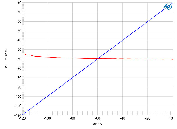
Here is my RMS measurement (versus dBFS) of the Yggdrasil2 (below) from its
unbalanced analog outputs (281 steps, 0.500 dBFS per step, from -140 dBFS to 0 dBFS):

The lowest step on the X-axis at which the plots in the above RMS linearity measurement have dBFS and dBrA levels within 1.00 dB of each other is -95.000 dBFS (left) and -98.500 dBFS (right). (Again, they're in 281 total 0.500 dBFS steps, which is why they end in either .000 or .500.)
As I've now said a few times, the Yggdrasil2 definitely performs better from its
balanced outputs (which you did not post, but did seem to run measurements from).
Here is my linearity error measurement of the Yggdrasil2 (below) from its
balanced analog outputs (281 steps, 0.500 dBFS per step, from -140 dBFS to 0 dBFS):

The lowest step on the X-axis at which the plots in the above linearity error measurement remain within 1.00 dB of 0.0 is -122.000 dBFS (left) and -117.500 dBFS (right).
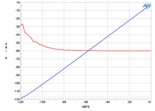
Here is my RMS measurement (versus dBFS) of the Yggdrasil2 (below) from its
balanced analog outputs (281 steps, 0.500 dBFS per step, from -140 dBFS to 0 dBFS):

The lowest step on the X-axis at which the plots in the above RMS linearity measurement have dBFS and dBrA levels within 1.00 dB of each other is -122.000 dBFS (left) and -117.500 dBFS (right).
Again, the performance from the balanced analog outputs is significantly better than from the unbalanced analog outputs (and, on these forums, as best I can recall, Schiit has always recommended using the Yggdrasil balanced). I'm not sure why you only included a balanced measurement for frequency response, but nothing else (e.g. linearity, etc.).
As for determining a DAC's resolution, when I find the time, I want to examine how John Atkinson from
Stereophile determine's a DAC's resolution in bits, which is certainly different than your +/- 0.1 dB linearity error standard. When I do that, I'll show the corresponding measurements for this DAC (and perhaps others).
NOTE: Stereophile's audio measurements have been published and available for decades, their methods and results subject to peer review (they're public), and their methods occasionally helped along by other engineers in the industry. As such, their work has largely guided and informed our measurements of audio electronics, and will likely continue to. That said, I will endeavor to add interesting and novel measurements (well, novel outside of R&D labs), like examining out-of-band performance and behavior, the ability of DACs to tolerate jitter (jitter that we control to deliberately impair the signal), and more.
@amirm, you are a member of the trade (MOT), and we do not allow MOTs to criticize and/or attack other MOTs here. Again, it's clear to me that you have an agenda and strong bias, especially where Schiit Audio is concerned. The only reason I allowed your post (the one I'm quoting in this post) to remain is so that I could respond to it and maintain the context for my response.
Of course, you are welcome to do whatever you want on
your website and forum, but (especially as you are a MOT) Head-Fi is not your dais to carry out your particular brand of bias. You seem to suggest that you let the measurements do all the talking, but I beg to differ. Sometimes your measurements fall silent in the shadow of your sensationalist narrative.
Again, the Schiit Audio Yggdrasil2 is a multi-bit DAC, and most of those who buy it are probably not buying it for the best measured performance, even though it does seem to me to measure well relative to other multi-bit DACs -- especially from its recommended balanced outputs. While plenty of other DACs are promoted by their makers as sporting 32-bit/768kHz DAC chips, Schiit Audio has always very openly described each of the Yggdrasil2's four AD5791 BRUZ DAC chips as 20-bit DACs. Your narrative suggests that you were perhaps the first to uncover the fact that multi-bit DACs generally do not measure as well as the delta-sigma types, as if it were a notion new to us all. It is not. Perhaps your next discovery is that tube amps don't measure as well as solid state ones? That turntables don't measure as well as digital sources?
If you want to have a private conversation via PM (or even telephone), then feel free to PM me.
All of my measurements in this post were made at Head-Fi HQ using the
Audio Precision APx555 audio analyzer.


_-140-0 dBFS_1 kHz_digi bal out_ana unbal in.jpg")
_-140-0 dBFS_1 kHz_digi bal out_ana bal in.jpg")
_-140-0 dBFS_1 kHz_digi bal out_ana bal in_AND_ana unbal in.jpg")
_-140-0 dBFS_1 kHz_digi bal out_ana unbal in_Y-dBrA.jpg")
_-140-0 dBFS_1 kHz_digi bal out_ana bal in_Y-dBrB.jpg")
_-140-0 dBFS_1 kHz_digi bal out_ana unbal in_Y-Vrms.jpg")
_-140-0 dBFS_1 kHz_digi bal out_ana bal in_Y-Vrms.jpg")

