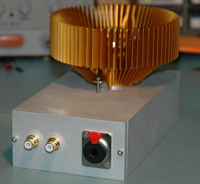
I wanted a Dynalo for my desktop rig and I wanted it to have the same length like my CDP, so I went for a "4 chamber" design: (1) transformer, (2) psu, (3) rca input + volume pot, (4) amp board. Each chamber consists of a standard eurocard-sized enclosure, tied together by a large front- and rear-panel made by FPE:
(click on pic for full scale image)
It would have been a shame to bury the precious amp board in a case and I wanted to admire the board from the outside while it is at work, so I implemented a window into the frontpanel. Additionally I always wanted an illuminated volume knob and finally made the present for myself
Amp board and volume knob are illuminated by blue LEDs of 2000mcd.
Wow mb3k, that really has come out looking very elegant. However, you might want to check into the PCM2702 datasheet as it states the max voltage being 5.5v.
Originally Posted by robzy Wow mb3k, that really has come out looking very elegant. However, you might want to check into the PCM2702 datasheet as it states the max voltage being 5.5v.
Rob.
Perhaps mb3k is going to use the onboard regulator to step down the voltage a bit further to around 5.3v? Just a speculation...
Originally Posted by doobooloo Perhaps mb3k is going to use the onboard regulator to step down the voltage a bit further to around 5.3v? Just a speculation...
In which case - that would make a lot of sense Feel free to ignore my comments mb3k, sorry.
Originally Posted by robzy In which case - that would make a lot of sense Feel free to ignore my comments mb3k, sorry.
Rob.
I'm wondering though... if the Welborne regulator is already pretty high quality, would there even be any benefit to running it through a second round of regulation?
Originally Posted by doobooloo Perhaps mb3k is going to use the onboard regulator to step down the voltage a bit further to around 5.3v? Just a speculation...
Yeah, I'm planning to use the on-board regulator.
EDIT:
I will have to use at least one regulator to get 3.3V, so I might as well use the other regulator for the 5V and if I want I could use an adjustable reg to get 5.4V.
Although I could set the PSReg to 5.4V, it's hard to find resistors with exact values to obtain 5.4 on the dot.
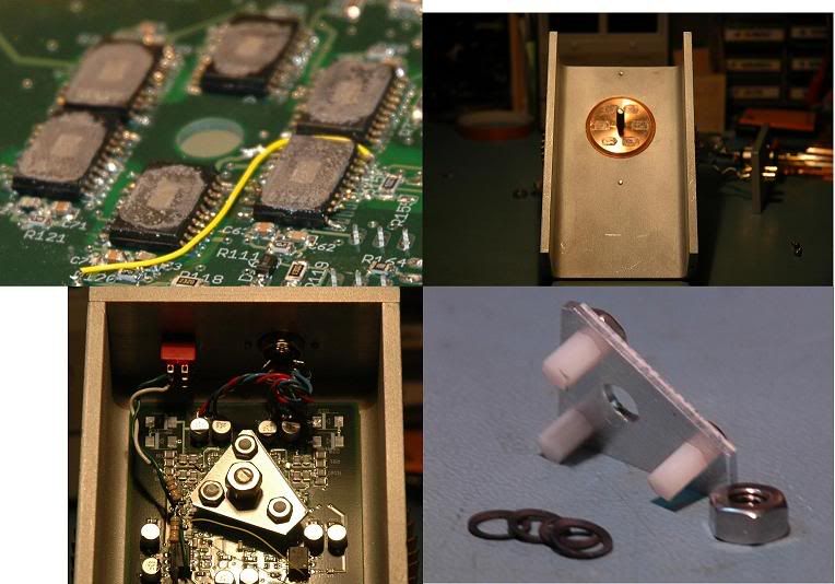
photos prompted by yet another thread saying it couldn’t be done – Class A Op Amp Headphone Amp - not the “usual Class A op amp bias with a Buffer” but Full Output Swing Class A Bias from Op Amps
The heat sink is a Zalman Golden Orb II, drilled and tapped for a ¼-20 ss socket head screw which protrudes from the center of the Cu slug bottom and to which the pcb carrying the TPA6120s is clamped
The 6 TPA prints of Artic Silver are visible on the Cu slug of the Zalman
The Al tripod has nylon pcb standoffs cut down to press on the pcb – the conical spring washers maintain clamping force
The TPA6120 op amps were laid down belly up on the pcb and each leg was bent down and soldered (how? – very carefully, with the aid of optics) – You can see I didn’t bother to bend down all of the legs – some are not connected internally in the TPA
The pcb turned out to be flat enough that even with the 6 packages there was only a few mil of unevenness – plenty small enough gap given the Artic Silver thermal conductivity (don’t get it on the circuitry – not formulated as a electrical conductor it still can be a problem)
I’m sure there are simpler solutions possible but I wanted a “universal” proto amp +/-24 V swing for Hi Z cans and +/-440 mA pk Class A for Lo Z cans – these #s give ~ 25 W total power dissipation in Class A for the 2 channels/6 TPA6120s
[heatsink discussion in "AD8397-class A?" DIY thread]
Wow. That's an amazing piece of engineering.
How does it sound? Does class-A biasing make a clear positive difference in sound?
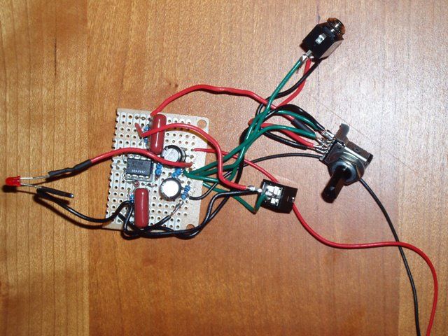
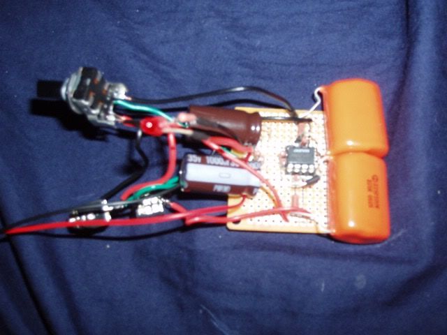
[size=medium]PIMETA Pairs[/size]
A PIMETA pair designed and built with perfboarded, LM317 (TO-92) Trickle Chargers. Trickle charger is designed so that wall-power is always charging at a very low rate, with plenty of reserve to power the amp. So with batteries charged, plugged or unplugged makes no difference. Walwart is a Jameco #174861 24VDC@500ma linear, regulated wallwart through a standard 2.1mm isolated (plastic) socket in the rear. The trickle charger and battery/power leads are nestled between the batteries. Charged battery life is approx. 4-6 hours without the walwart.
470uF Nichicon UPW (10x16mm shorty's)
Double stacked BUF634, single on Gnd, Class A bias trannies
AD8066/AD8065 in one, AD8620/AD8610 in the other
Batteries are 8.4V, 250mah from the Shoreline Market on Ebay.
Hammond 1455J1201 cases
The design/build thread was most recently documented here: Trickle Chargers
Tangent recently made LNMP boards available. I have wanted one of these tools for some time now and found it to be a fun and interesting build. Pretty much stock except I added a trim pot to the 3rd gain stage to independently calibrate the 100 and 1000x gain settings.
This site uses cookies to help personalise content, tailor your experience and to keep you logged in if you register.
By continuing to use this site, you are consenting to our use of cookies.


")


 Feel free to ignore my comments mb3k, sorry.