


sedan delivery
Head-Fier
- Joined
- Mar 28, 2007
- Posts
- 79
- Likes
- 0
Very nice,indeed.


| Originally Posted by Llama16 /img/forum/go_quote.gif WOW!!! I feel so humble when looking at all these homemade amps. I hope to one day be able to get the parts together to build myself one hell of a nice amp and have the right to post here
Well currently I'm building 2 cmoy's at once. As this is the first time I ever came in contact with soldering and handling electronics on this level please excuse me of my o so sloppy work, I'm really just getting into this. I made the one from tangentsoft, justa cmoy to be able to run my HD650's of my ipod for now, later on I will build some more dedicated ones as soon as I finish this cmoy with succes. On the left is the practice one, and on the right I am trying to clean it all up. I'm still waiting for my opamp and input jacks: http://img18.imageshack.us/img18/5412/1013238.jpg[IMG] On the back thee practice one is even more sloppy (I still need to make the connections on the clean one, so I'll only upload the practice amp)... don't freak out!!: [IMG]http://img16.imageshack.us/img16/861/1013243.jpg[IMG] I still don't have a clue how to connect these: [IMG]http://img16.imageshack.us/img16/853/1013245m.jpg[IMG] As I already said: this is my evry first contact with soldering, electronics, .... I hope to learn alot more this easternholiday because I've already got big plans...I hope to sell some later on, make some small profit, and buy parts for a PIMETA. Great job to all of you, I am astonished and hope to be able to know as much as you all do one day.[/i] [/td] [/tr] [/table] What you are doing here is absolutely great work, you are already ahead of a lot of people on here. Keep using those protoboards, you'll learn a lot with them |


| Originally Posted by Llama16 /img/forum/go_quote.gif WOW!!! I feel so humble when looking at all these homemade amps. I hope to one day be able to get the parts together to build myself one hell of a nice amp and have the right to post here. Well currently I'm building 2 cmoy's at once. As this is the first time I ever came in contact with soldering and handling electronics on this level please excuse me of my o so sloppy work, I'm really just getting into this. |
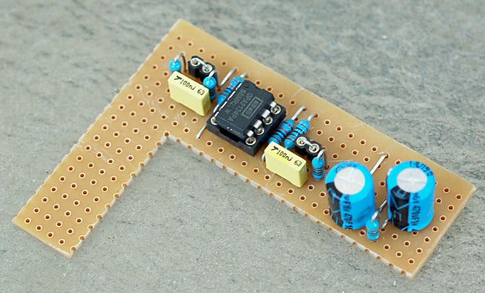
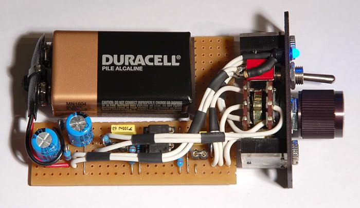
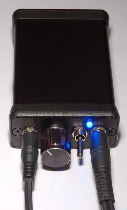
| Originally Posted by Laika /img/forum/go_quote.gif My first post and my first Cmoy build
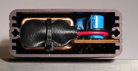
Pretty much a stock cmoy build, power caps are 470uf and the sockets are for the optional output resistors. Since the pics were taken I have socketed the gain resistors (now @ 6x) and after some reading I may increase the value of the input caps for better bass handling. It turned out better than I had hoped
|
| Originally Posted by Laika /img/forum/go_quote.gif My first post and my first Cmoy build
Pretty much a stock cmoy build, power caps are 470uf and the sockets are for the optional output resistors. |

| Originally Posted by Laika /img/forum/go_quote.gif Thanks Fred and Forte, I've built a couple of guitar effects before so I'm getting better at keeping things tidy. |

| Originally Posted by DaKi][er /img/forum/go_quote.gif What you are doing here is absolutely great work, you are already ahead of a lot of people on here. Keep using those protoboards, you'll learn a lot with them |

