Post pics of your builds....
Jan 23, 2007 at 4:21 AM Post #1,786 of 9,811
Quote:

Originally Posted by Buzzerbro /img/forum/go_quote.gif
Hello, I recently cased up my PPAS amplifier. I added a Bass Boost circuit and used over speced caps.


Cool way to light up the jack. How was the SMD soldering?
 
Jan 23, 2007 at 4:36 AM Post #1,787 of 9,811
rsaavedra, beautiful work. I really like the look of that amp and all of the work and innovation that you have put into the cases. Awesome job and I hope that you enjoy it!! Congrats on a job well done
smily_headphones1.gif
 
Jan 23, 2007 at 5:02 PM Post #1,788 of 9,811
I built this phono preamp to listen to vinyl on my system (duh). It's based around ESP's multi-stage active/passive RIAA equalization scheme. I designed a toroidal transformer, regulated power supply. I based the layout around 4 single channel opamps, as this gives the greatest versatility for switching op-amps. Originally I had OPA134's installed in all four locations, however the LED power wire moved during testing and shorted to the incoming 120VAC power line, and blew a lot of stuff up, including the chips. The only other single channel op-amps I had were LM741's (I already slapped myself, don't worry), and CA3140's in the old school round metal cases, and used two of each in the meantime. Today I got 4 OPA228's and put them in. These are now pretty much my favourite op-amps ever. While proper implamentation makes much more of a difference than the opamps themselves, these are just fantastic chips. The sound isn't warm and tubey, or cold and analytical, it's clean, it's present and it's awesome.


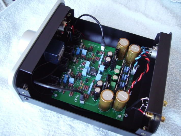
This of course is the inside. I don't mind vera board for one-off projects like this.


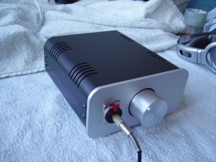
The back, input/output through RCA jacks. These are insulated from the chassis ground, to ensure the prevention of ground loops. The switch on the rear panel is a ground lift switch. It's useful for different grounding scenarios, where being able to disconnect the mains ground becomes exceptionally useful to minimize hum. The ground connection is an insulated banana plug connector.


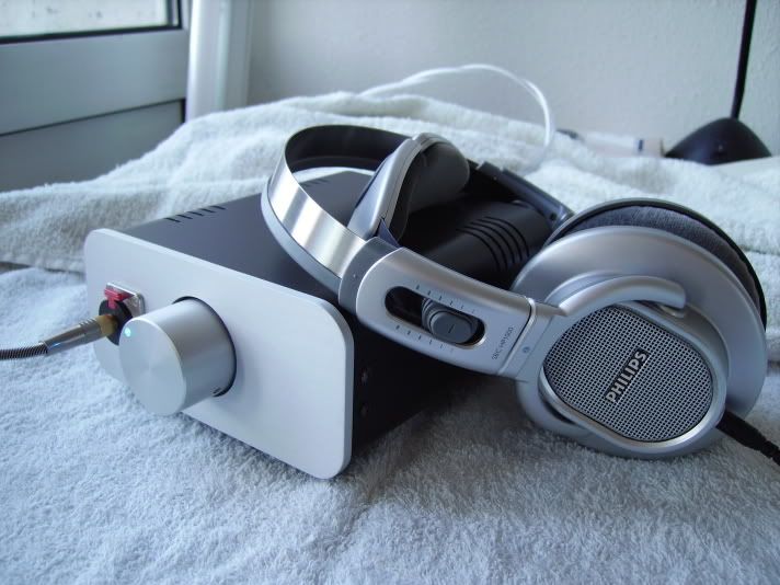
Professional 2U high panel front, for eventual rack mounting. Minamilist styling, with an LED rocker switch in the middle of the front panel. All in powder coated black. Anyway, thought you guys might like to see.
 
Jan 24, 2007 at 6:08 AM Post #1,789 of 9,811
Quote:

Originally Posted by n_maher /img/forum/go_quote.gif
Namely, switchable inputs (internal Alien DAC and 1/8" input), TREAD power supply, and 1/4 or 1/8" output.
73089339.jpg


Hey Nate! Nice work, mate! You work pretty fast. For the Alien DAC, are you using power from USB? I did not see any direct connection to the Tread.

Quote:

Originally Posted by n_maher /img/forum/go_quote.gif
And special thanks go out to MisterX without whom the Alien DAC would still be non-functional.


Well, who else would be so kind!
icon10.gif
 
Jan 24, 2007 at 2:00 PM Post #1,790 of 9,811
Quote:

Originally Posted by bhjazz /img/forum/go_quote.gif
Hey Nate! Nice work, mate! You work pretty fast. For the Alien DAC, are you using power from USB? I did not see any direct connection to the Tread.


Thanks! And yes, the Alien is USB powered - it's the easiest configuration as far as I can tell.

With a little luck you'll see some more pictures of a different, much larger project in the next couple weeks along with a few other smaller ones. I've been rather busy lately.
evil_smiley.gif
 
Jan 29, 2007 at 4:26 AM Post #1,791 of 9,811
The Soha is sold, all hail the Soha! The name of the new Soha is "When SOHA goes BAD!"
biggrin.gif


Terrible time casing it, but after hours of work, it looks nice and appropriate with the red lighting. Yes, that actually is a little screw at the top of the case beside the tube protector and yes, it's purely cosmetic
smily_headphones1.gif


ELNA Silmic II and Mundorf MCap ZN's in signal path.
Panasonic FM's power supply except for 100uF/100V Nichicon UPW
Electro-Harmonix tube (Switching JJ & EI)
Working on DB's at the moment so listening to OPA2107 as buffer.

 
Jan 30, 2007 at 10:26 PM Post #1,792 of 9,811
Here is my first Alien DAC. It actually went together quiet smoothly, the trick was lots of flux, a fine tipped iron, and patience. I just checked for bridges with the DMM and cleaned them up with braid.

P1010011.JPG


The SMD also went well, but the 0805 size was intimidating to say the least. I've done 1205 size the Millett Diamond buffers, but these are tiny! It also didn't help that my tweezers were slightly magnetic, when I tried to let the part go, it would be stuck to the tweezers! Time for a nice pair for electronics I say.

P1010014.JPG


Then to case it up, I measured where the USB jack would be and scoured lines on the inside of the case to mark it's position. I drilled a round hole as large as I could, then used a file to make it square. As I got close to the lines, I just checked the fit with the board. Turned out great!

P1010024.JPG


And couple of jacks on the other side...

P1010025.JPG


There you have it, an Alien DAC. Thanks to all those who put so much work into this fun project! For more/larger pictures go here.
 
Jan 31, 2007 at 7:26 AM Post #1,793 of 9,811
Feb 2, 2007 at 5:31 AM Post #1,794 of 9,811
A new SOHA is made!

I was so taken aback by the incredible casing rsaavedra did on his Dynahi, I was inspired to make something in a wooden box as well.

This is my new SOHA. It's the same config as before (look 3 posts up), plus an AC power filter, same design as in Tangent's STEPS. I think it turned out very well. The insides of the box reveal some turmoil through the casing process, but who's looking inside anyway?
smily_headphones1.gif


Without further ado, pics! With the size of the box, everything else has been moved from the desk and the AlienDAC hidden behind it. The photo on top of the box is my sweetheart, Violet
smily_headphones1.gif


Feb 2, 2007 at 7:30 AM Post #1,795 of 9,811
Welcome to the club!
biggrin.gif


Could you explain abit of that AC filter? How simple is it and how does it work. Our apartment's AC-line is really crappy, and I hear snaps every time the fridge starts and stops cooling itself. Sometimes even switching lights on creates audible distortion. I dont even want to mention the hum when the oven is on...
wink.gif


Quote:

Originally Posted by FallenAngel /img/forum/go_quote.gif
A new SOHA is made!

I was so taken aback by the incredible casing rsaavedra did on his Dynahi, I was inspired to make something in a wooden box as well.


Feb 2, 2007 at 2:09 PM Post #1,796 of 9,811
The one I built was straight from Tangent's STEPS. A little more info here and I'm sure there are some better line filters, but I recently built a STEPS for the PPAv2 and had doubled of all the line filter parts (about $10). I used the second diagram, but put the transformer before the last 0.1uF cap and 100 Ohm resistor, exactly like in the STEPS schematic.

It's really easy to build on breadboard, took about 15 minutes and that's including wiring the transformer.

Since I have it right beside my computer, cordless phone, wireless keybaord and mouse as well as a really bad printer that always sets off my UPS power supply by adding noise to the line, I thought it would be a worthwhile build. I didn't need a surge suppersor (simply add 2 varistors into the circuit as per Jon Risch's schematic) because it's built into my UPS, but a DIY line filter is nice to have. I can definitely say that this one sounds better than the one a few posts back, but that's probably because I like the JJ tube more with my setup. It's darker and more relaxed unlike the EI tube that's very active.
 
Feb 3, 2007 at 4:42 PM Post #1,798 of 9,811
Quote:

Originally Posted by Ferrari /img/forum/go_quote.gif
CK3


OMG those ATI's cases are beautiful. Wish their shipping would be cheaper...
biggrin.gif


EDIT: Yeah, and none taken away from the awesome building style you have Ferrari. Excelent piece!
smily_headphones1.gif
 
Feb 3, 2007 at 8:43 PM Post #1,799 of 9,811
Thanks Yen!

Some details of my build: It's indeed housed in an ATI-735U enclosure while the 24VA power transformer, netfilter and fuse are housed in a separate "wallwart" to minimize magnetic field interference. Clip-on heatsinks are applied to the output transistors (Toshiba 2SC2238/2SA968) and the quiescent current was set to 40mA. The electrolytic capacitors are Nichicon Muse FX, FW and HN. Philips (BC) MKC/MKT film caps and polystyrene are used throughout. Vishay-Dale RN55D resistors are used in most part of the amp and the volume control is a blue Alps RK27.

This CK²III is an easy to build but very good sounding amp. I love the sound this amp produces... it makes DIY so fun
340smile.gif
!

Afbeelding034.jpg


Afbeelding042.jpg
 

Users who are viewing this thread

Back
Top