Post pics of your builds....
Jan 15, 2007 at 12:19 AM Post #1,771 of 9,811
037a.jpg


bh6.jpg


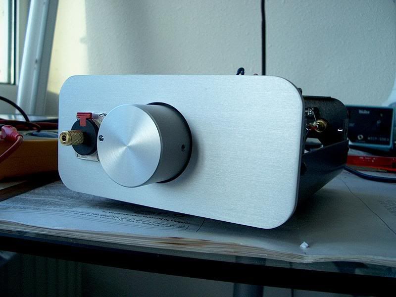
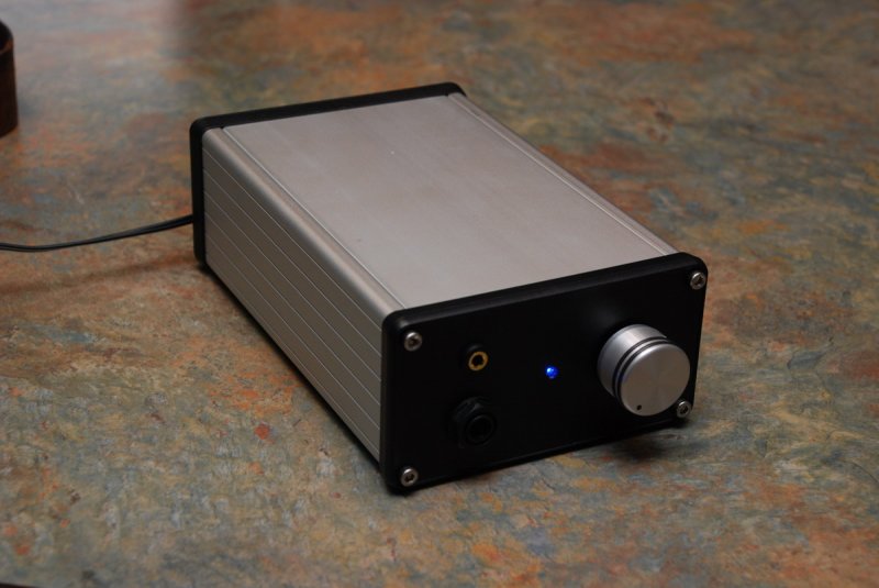
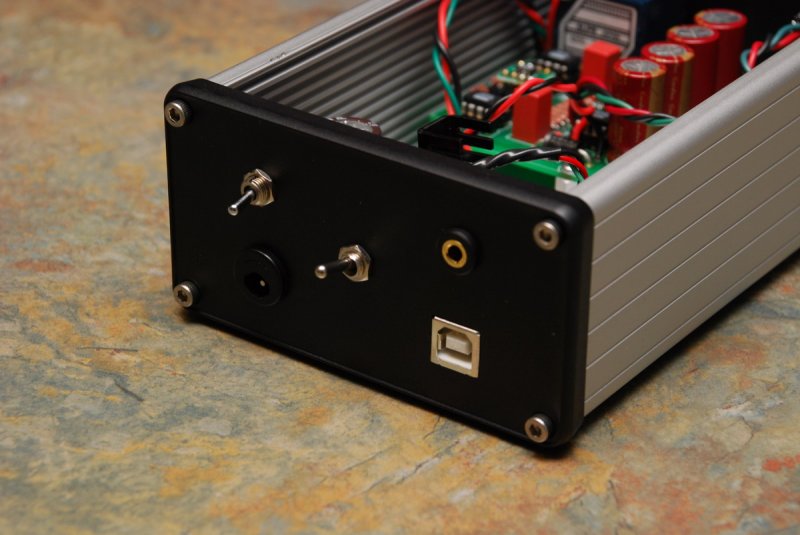
Created the boards from files right befor Halloween, and she came to life this past Friday night. The cheapie HK attenuators were replaced with GoldPoints, and I'm burning everything in with some budget JJ EL34.

Calamities:

1) The cheapie attenuators off eBay are a bargain - because they are crap, at least the ones from HongKong (AcidMilk). Unfortunately, I ordered good MONO attenuators from Taiwan (sweet Holco units), but, alas, this needs dual stereo. GoldPoints to the rescue - at ~$300. Total right (and wrong) attenuators - $450 & 3 weeks lost to waiting...

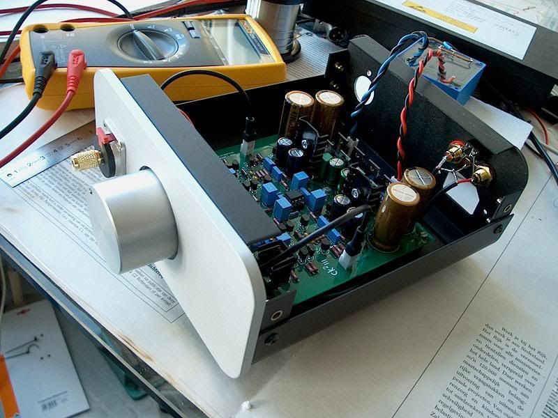
2) Finish the metal casework before mounting any electronics. In a panic, I had the wrong XLR connectors, and rather than pull the boards, I just drilled bigger holes, and vacumed out the shavings. WRONG! Some shavings mixed with a bit of excess thermal grease, and stuck to the bottom of a transistor - oh, well, nothing like 4 scorched 2sa1968, a handful of resistors and LEDs to take the wind outta the sails - well, and 20 fuses to help troubleshoot the problem.

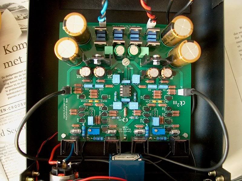
3) Have good fortune to ask the right question at the precise right moment. The board files have a quirk with one of the standoff routings, where, after an hour or so of operation, the trace running too close by eats away the seperation, and things go south, quickly. By the grace of God, Alex asked Justin, and he warned about this - mere hours before disaster. Fiber insulators were inserted, and apocalyptic doomsday averted.

4) Have a good friend who is willing to QC your work and help determine What is wrong when all this happens. I was indeed lucky that Alex is close, and interested in this build. It really does take a village.

This was WAY more of a challenge than the Millett and m³ (x2) units I have built in the past, mainly because there was NO BOM (and yes, I do have a good one, finally), and the ultimate thanks go to Dr Gilmore for the fabulous tribute to the STAX T2, and to Justin, who stepped right to prevent a calamatous cluster with a boards design flaw.

Total cost: Well, for the parts actually used, ~$1500, and about $2k with fraud, waste, abuse, and rework.
 
Jan 15, 2007 at 2:31 AM Post #1,772 of 9,811
Defiantly a long search processes of what went wrong it was. At least it was finished and completely working now. Having listened to the amp for 2 days after fixing it I am defiantly going to be ordering my parts soon to make the build for one of my own. Enjoy one of the best electrostatic amps out there!

-Alex-
 
Jan 15, 2007 at 4:47 AM Post #1,773 of 9,811
I recently found myself in the position of needing to replace the amp in my office rig. While trying to come up with ideas I happened to look around my work bench and was staggered to find the pieces of several uncompleted projects. Shocking, I know! Looking at this pile of parts, pcbs and half-done builds I realized I pretty much already had everything I needed. So I set out this weekend to case it up and have it ready for my return on Tuesday. The result is a pretty neat little PIMETA with a few tricks up it's sleeve. Namely, switchable inputs (internal Alien DAC and 1/8" input), TREAD power supply, and 1/4 or 1/8" output. And here are the pics:

Full View
73089338.jpg


Front

73089341.jpg


Back
73089340.jpg


Guts

73089339.jpg


I'm pretty pleased with how it turned out and can't wait to put it into service. Well, actually I can since that means I'll be back at work but it'll go a long way towards making work more bearable. And special thanks go out to MisterX without whom the Alien DAC would still be non-functional.
 
Jan 16, 2007 at 1:58 AM Post #1,774 of 9,811
More shots of my Dynahi's still undergoing enclosure work:


Unlined interior of the PSUs enclosure: originally I had the aluminum screen attached with some U shaped nails, that's why there are those spider-like bites all over the place. The little blocks of wood are to lift the power supply units a bit from the bottom, so that the large transistors on their surface float and don't touch the bottom of the enclosure. (The transistors btw are covered with 4 layers of electrical tape to protect them from touching the grounded screen):

aluminum-lined_enclosures_walls_001.jpg


Aluminum lining partially done. Before applying the aluminum tape decided to cut a few ravines between some of the holes, so as to have even more ventilation:

aluminum-lined_enclosures_walls_002.jpg


Enclosure fully lined, with the screen placed and secured to the bottom. Connectors and gadgets in the box all ready:

power_supplies_enclosure_interior.jpg


Glue in the aluminum tape is non-conductive, no surprise there. The cooper strips and green wires are for proper grounding of all the aluminum strips in all enclosure walls, top and bottom.


The interior of all panels for the two enclosures. Three still to go, including the front panel of the amp, but getting close to done...

aluminum-lined_enclosures_walls_003.jpg


Update II: The exterior of the enclosure now almost ready. Also have to clean some dirt on it, the black finish is unforgiving of any dust. Back panel needs painting still, and some minor points here and there need wood filler and paint. But PSU's enclosure 99.9% done:

power_supplies_enclosure_exterior_002.jpg


power_supplies_enclosure_exterior_001.jpg


Never underestimate the saying "measure twice, cut once". Can you spot a couple of tiny holes that eventually weren't used?

power_supplies_enclosure_exterior_003.jpg


Testing everything, umbilical cord connecting PSU box and rear panel of the main box.

Testing_Dynahi_power_supply.jpg


Update III: Final interior of the PS box, bolts+nuts attaching the PSU's to the base, some electrical tape placed on top of some electrical points, and some extra cable ties here and there:

Condor_Power_supplies_002.jpg
 
Jan 20, 2007 at 6:36 PM Post #1,775 of 9,811
Here a few more pics of the progress in my Dynahi amp enclosure.

First, a shot of a little board I put together to make the star ground point:

star_ground_point_001.jpg


Wired the connectors to the "root" connector" (center of the star) using solid silver wires laid out as diverging branches. Check the cuts on the boards' copper runs, in order to prevent lateral conductivity between the silver branches. The pic was taken before final version which had extra cuts between the outer-most branches and the attachment holes:

star_ground_point_002.jpg


Here's the little board attached to the enclosure base already, using bolts and nuts, and 0.5" nylon spacers:

dynahi_amp_progress_001.jpg


A closer look. That red cable (a shielded microphone cable) goes through a switch to power the LED. Going the purist way
tongue.gif
Even though I added a 100K resistor in series with the Led to reduce its brightness to comfortable levels, decided to have that ability to turn off the LED completely, leaving all power feeding nothing but the sound circuitry:

dynahi_amp_progress_011.jpg


Back panel:

dynahi_amp_progress_008.jpg


Signal path between RCA ins and the Alps blue, shielded (and grounded) microphone cables inside a grounded steel jacket. The little blue wire is to ground the front surface of the Alps blue. I will probably add a copper shield for the Alps Blue btw:

dynahi_amp_progress_004.jpg


Rear view of all front panel components attached to it:
dynahi_amp_progress_003.jpg


And front panel view:
dynahi_amp_progress_009.jpg


Have to do some more drilling and painting, and attach the different panels of the enclosure, but it's basically done. No clicks when moving the pot (as opposed to when using the Elma) and now with this EMI rejection shielding of the input signal path, there's no humming whatsoever with player paused and volume at max. Even with the PSU less than a foot away, basically next to the input wires and RCA ins, while having the amp enclosure actually open (not fully assembled) as shown in the pics. This is quite an improvement over the PSU proximity sensitivity of my original enclosure. Listening to Brothers in Arms right now, sounding amazing...
 
Jan 21, 2007 at 5:17 PM Post #1,776 of 9,811
Holy bananas, rsaavedra, that thing looks like it's going to be used for critical listening by the crew of a sun probe. :p Are you shooting for a job at JPL or NASA?
 
Jan 21, 2007 at 7:39 PM Post #1,778 of 9,811
Quote:

Originally Posted by Girlsound /img/forum/go_quote.gif
Holy bananas, rsaavedra, that thing looks like it's going to be used for critical listening by the crew of a sun probe. :p Are you shooting for a job at JPL or NASA?


LOL, no not really, but hey you never know, some astronauts might like good sound
biggrin.gif
 
Jan 21, 2007 at 10:09 PM Post #1,780 of 9,811
Quote:

Originally Posted by mb3k /img/forum/go_quote.gif
Where did you get those connectors for the inputs and outputs?


The audio inputs (L/R) and power connectors on the PCB are from the kit I bought from jrossel. This is the Molex KK 22-23-2021 0.100" header, 2-circuit (Mouser 538-22-23-2021; Digi-Key WM4200-ND) and the mating plug 22-01-3027 (Mouser 538-22-01-3027; Digi-Key WM2000-ND), as recommended at AMB CK2III website.
 
Jan 22, 2007 at 6:11 AM Post #1,781 of 9,811
And finally, I have finished the enclosures for my Dynahi after so long. Here some pictures.

First, the final interior of the main and power supply boxes:

pot_relocation_knob_extension_004.jpg


Condor_Power_supplies_002.jpg


More pics preparing the interior of the enclosures, and much earlier ones, assembling the transistor sandwich.


Now about the exterior, here's the boxes right before a final application of paint. I used strips of that self-sticking vynil weatherstrip shown on the right as "feet" along the bases of the side walls. The boxes sit really comfortably anywhere with those as feet:

dynahi_amp_enclosures_finished_009.jpg


The boxes seen from the bottom. They look like buildings of some sort, or some strange sculptures
tongue.gif


dynahi_amp_enclosures_finished_012.jpg


Here's applying the paint. A can of the paint used (Krylon BBQ & Stove) is shown on the right. That paint can take up to 1200 F (649 C). Not that the amp is travelling in a sun probe, but doesn't hurt that it can withstand the heat.
biggrin.gif
Now seriously, I really like the finish this paint provides when applied on wood.

dynahi_amp_enclosures_finished_011.jpg


And here they are, at last!!! Well... that screw in the top middle needs a little retouching though
tongue.gif


dynahi_amp_enclosures_finished_021.jpg


Here's a view of the back panels. Some corner retouching also needed there
tongue.gif
The Quail hospital grade power cord shown to the right. That's the one I got about 2 years ago from the group buy for my Dynahi, finally will get some frequent use. The umbilical cord to connect the two boxes is shown on the left, that one I made myself:

dynahi_amp_enclosures_finished_022.jpg


Here's a few pics of details. You can spot that the finish is really a bit rough, not really incredibly polished, but I like to leave it at that level "hand-made" rough look. The rear corner retouching I'll take care of though
tongue.gif


dynahi_amp_enclosures_finished_030.jpg


dynahi_amp_enclosures_finished_024.jpg


dynahi_amp_enclosures_finished_025.jpg


dynahi_amp_enclosures_finished_032.jpg


dynahi_amp_enclosures_finished_033.jpg


Here's the setup singing, using a Bel Canto Dac2 (loaned by Gene) as source, Toshiba 3950 as transport, sounds great! The stuff in the background belong to my parents (went to their house to do the painting in their garden
tongue.gif
):

dynahi_amp_enclosures_finished_018.jpg


And a couple more pics for fun:

dynahi_amp_enclosures_finished_005.jpg


dynahi_amp_enclosures_finished_023.jpg


dynahi_amp_enclosures_finished_017.jpg


component_stack.jpg


PS. Signature finally updated, with "Dynahi" linking to this post #1781. (To think I started my Dynahi more than two years ago, by the time of post #71 in this same thread).

PS. II. Heatsink extension improvement.

PS. III. Shortening the signal path (relocating the volume pot.)
 
Jan 22, 2007 at 1:38 PM Post #1,782 of 9,811
This is a wonderfull Dynahi you've got there, you sure seem to have put lot of time on it, but in the end this is what separate great looking project to Ok project i think. Congratulation
icon10.gif
 

Users who are viewing this thread

Back
Top