Post pics of your builds....
Dec 30, 2006 at 6:46 AM Post #1,711 of 9,811
**56K WARNING**
frown.gif


Finished my Millett Hybrid today. Right now i'm running it on a cd player and my ksc-75s for an hour or more to make sure it wont go haywire on my good phones. Seems to be working great so far though.

heres some pics of it from its premature stage to finished:

heres one of the caps and resistors, well most of them...i got delayed for a day because i bought two too little film caps, and didnt know what the rled resistor was
tongue.gif
then i realized it was a normal resistor, they just made the price list funny.

progress3xg2.jpg


my tube socket leads didnt fit through the holes so i had to solder them ontop

progress22mf3.jpg


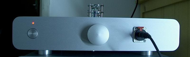
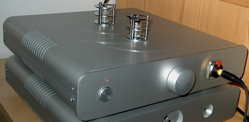
and finished picture one

finished6gy1.jpg


and a full picture

finished3yk7.jpg


and the pot i settled on, which worked out even better imo. Not sure what the resistance is, but i tested it with my fluke and it was the most spread out of the ones i had.


the bottom, only a few blobs on there
rolleyes.gif


and a picture of it hooked up (walkman > inter-connect i just built > amp > ksc75s)


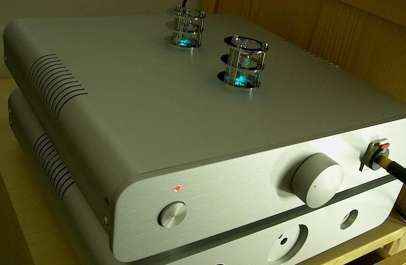
*I am currently using a 25v wall wart with it, but i plan on making a power supply soon, and i havent added leds under the tubes :-\

**I made it for my computer, and i plan on making a nice wooden enclosure for it early next week before finals start. It's going to be AV710 > millet > hd580s

***Please tell me if you notice anything wrong with it, like missing components!

-Thanks for looking!
 
Dec 30, 2006 at 7:24 AM Post #1,712 of 9,811
Just finished this today, didn't think it belonged it belonged in the alien dac thread...It's the same PCM2702 type circuit but on a smaller (1"x2") home made PCB with some of my own refinements.

Pictured here first (next to a CF card for scale) without output caps/connector, then in "action".

usbdac01btu4.jpg

usbdac02ao7.jpg
 
Dec 30, 2006 at 8:11 AM Post #1,713 of 9,811
i did a 4 sec exposure of the tubes with the light on in the room for the first like 1/2 sec so you can see outside and tube light:
finishedlithalfur6.jpg
 
Dec 30, 2006 at 8:23 AM Post #1,714 of 9,811
Quote:

Originally Posted by cyclopia /img/forum/go_quote.gif
pi5.jpg


That's a disgustingly sick case...
 
Dec 30, 2006 at 8:34 AM Post #1,715 of 9,811
my millett hybrid makes the music worse :-\ is makes all the highs and louder parts crackly and distorted? do i have to set the taper pots or something or what?
 
Dec 30, 2006 at 10:41 AM Post #1,716 of 9,811
That is a nice layout gontran.

I especialy like the creative layout for the output caps.
Now we just need more and more amps of this size
600smile.gif


Quote:

Originally Posted by Gontran /img/forum/go_quote.gif
Just finished this today, didn't think it belonged it belonged in the alien dac thread...It's the same PCM2702 type circuit but on a smaller (1"x2") home made PCB with some of my own refinements.

Pictured here first (next to a CF card for scale) without output caps/connector, then in "action".

usbdac01btu4.jpg

usbdac02ao7.jpg


Dec 30, 2006 at 2:17 PM Post #1,719 of 9,811
ggta,

I bought the enclosures directly from ATI. The power button on the upper enclosure is from ATI, and they indeed made the cut for the button. The cuts on top for the tubes are made by me. The cuts on the lower enclosure are also made by ATI. I'm going to use this one for my next project: the β22.
 
Dec 30, 2006 at 4:32 PM Post #1,720 of 9,811
So I finally finished my switch box yesterday and thought I'd share the pics. The knob shown is only temporary I'm going to get a different one thats larger. It switches one input RCA to four outputs RCA + 3x1/8" Mini. I'm going to use it to switch the output of my alien DAC (MacBook) between my Little Dot II+ and my workstations line in which happens to be connected to my speakers.

Box_Front.JPG


Box_Back.JPG


Box_Top.JPG
 
Dec 30, 2006 at 7:57 PM Post #1,722 of 9,811
Quote:

Originally Posted by labmat /img/forum/go_quote.gif
So I finally finished my switch box yesterday and thought I'd share the pics. The knob shown is only temporary I'm going to get a different one thats larger. It switches one input RCA to four outputs RCA + 3x1/8" Mini. I'm going to use it to switch the output of my alien DAC (MacBook) between my Little Dot II+ and my workstations line in which happens to be connected to my speakers.

Box_Front.JPG


Box_Back.JPG


Box_Top.JPG


Messy wiring but as long as it work well!!!
 
Dec 30, 2006 at 8:14 PM Post #1,723 of 9,811
Quote:

Originally Posted by Gontran /img/forum/go_quote.gif
You could mount the DAC inside there and save the degradation of multiple connectors and cables...


tongue.gif
You took the words right out of my mouth... I'm a little strapped for cash now but my plans are to mount an alien DAC and a tread to power it inside the box with another switch to switch between an external source and the alien DAC.

I'm also going to tidy up the wires soon and re-heat shrink over the solder joints on the rotary switch. My main goal yesterday was to make sure it worked; I messed up the circuits several times.
 
Dec 30, 2006 at 9:20 PM Post #1,724 of 9,811
My PIMETA.

Specifications:

-Hammond 1455N1201 clear extruded aluminium enclosure.
-Alps RK27 Volume pot, aka Alps "Blue"
-Elna Cerafine rail capacitors
-Wima MKS fast reservoir capacitors
-Matched Vishay-Dale resistors
-Socketed gain and buffer bandwith resistors, allows easy tuning
-Class A biased using matched transistors
-1 SMD buffer per channel (bottomside of the board) and 1 DIP8 buffer on the L/R channels
-OPAMPS (in order of preference): AD8620/10, OPA637/627, OPA627 AD8066/65, OPA2227/227, OPA2134/134
-Dual RCA inputs using Nkk switch (silver plated contacts)
-1/4" Neutrik output jack
-Kilo International Volume knob
-24AWG Silver plated copper wiring(done on the underside of the board, allows easy access to the board for easy chip rolling)
-Silver solder

I have built it about one year ago, but never finished the casework. I had some spare time last friday and this is the result (excuse my poor photography skills):

Before:
P4150125up.JPG


After:
P1010298up.JPG


Front Panel:
P1010312UP.JPG


Back Panel:
P1010311up.JPG


Detail of the dual imput switch:
P1010302up.JPG


The LED and ON/OFF switch are not perfectly centered because the panel was not well secured and it moved while drilling, but overall I am pleased with the results.

The power jack wiring is still temporary because I will install a TREAD power supply to use with a external AC/DC wallwart, but I need to get some mounting hardware from my local store.

The panels are not screwed in yet because I aparently lost the screws...
 
Dec 31, 2006 at 8:23 AM Post #1,725 of 9,811
Quote:

Originally Posted by labmat /img/forum/go_quote.gif
So I finally finished my switch box yesterday and thought I'd share the pics. The knob shown is only temporary I'm going to get a different one thats larger. It switches one input RCA to four outputs RCA + 3x1/8" Mini. I'm going to use it to switch the output of my alien DAC (MacBook) between my Little Dot II+ and my workstations line in which happens to be connected to my speakers.


Looks real neat. Thinking of making a similar switchbox. Would you like to share what switch you used and also what did you use for the wiring.

Thanks.
 

Users who are viewing this thread

Back
Top