All,
So i opened up my XDP-300R this evening. I took a few pictures along the way but couldn't do a video and to be honest you wouldn't want to hear me cursing throughout! Also they were taken on my phone so aren't great.
First off you do this (if you choose to) at your risk. You'll also void your (somewhat useless) warranty.
You'll need some tools commonly used to open mobile phones, I'll list what I used as I go. Now I'm going to keep this brief as to be honest if you aren't confident or competent doing this kind of repair or disassembly then you honestly shouldn't try, there's a lot at risk and you should probably have done something similar in the past.
Anyway here is goes.
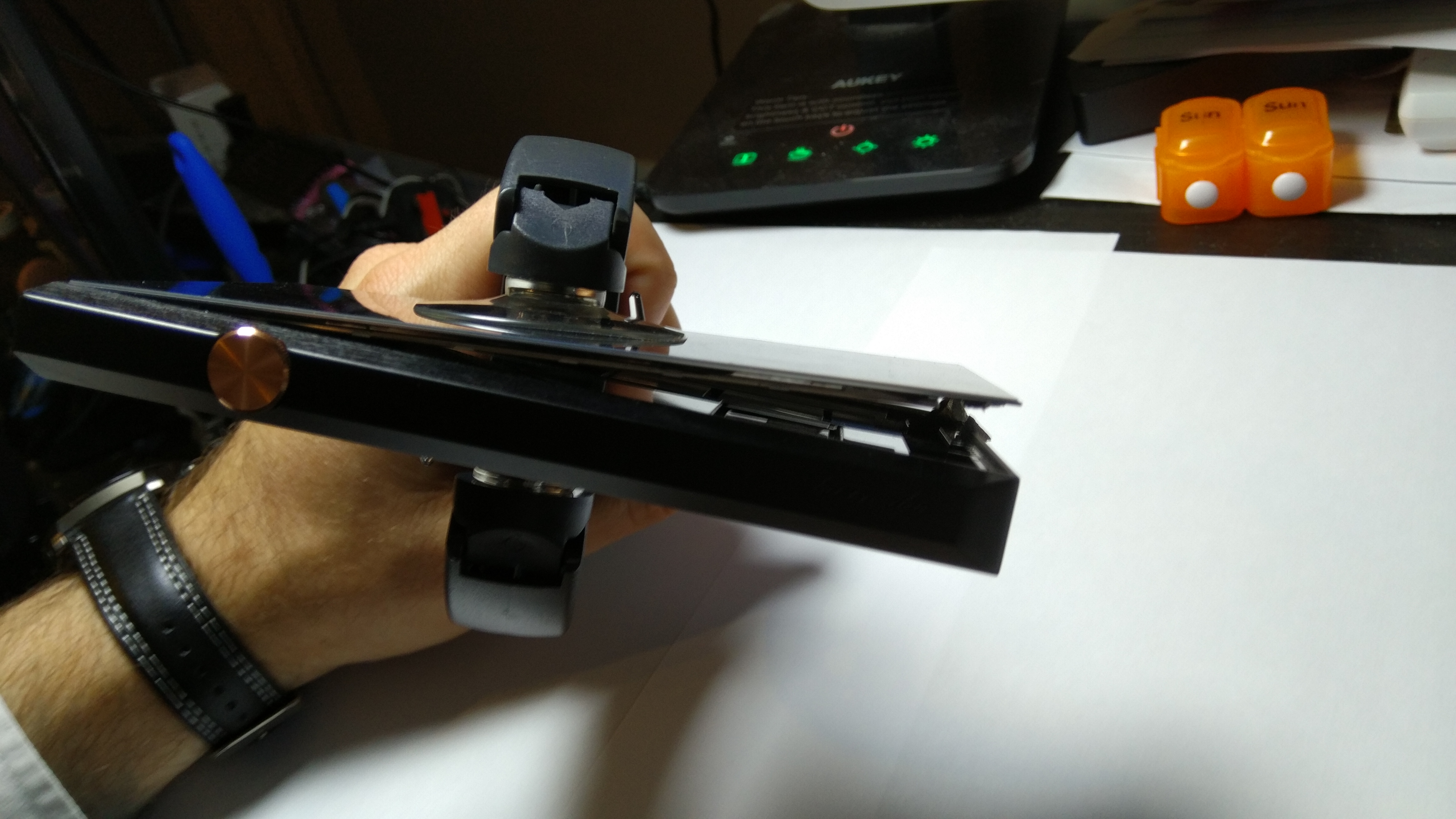
Firstly heat the screen with a hair dryer. Do not overheat, I heated the screen so it was warm to touch.
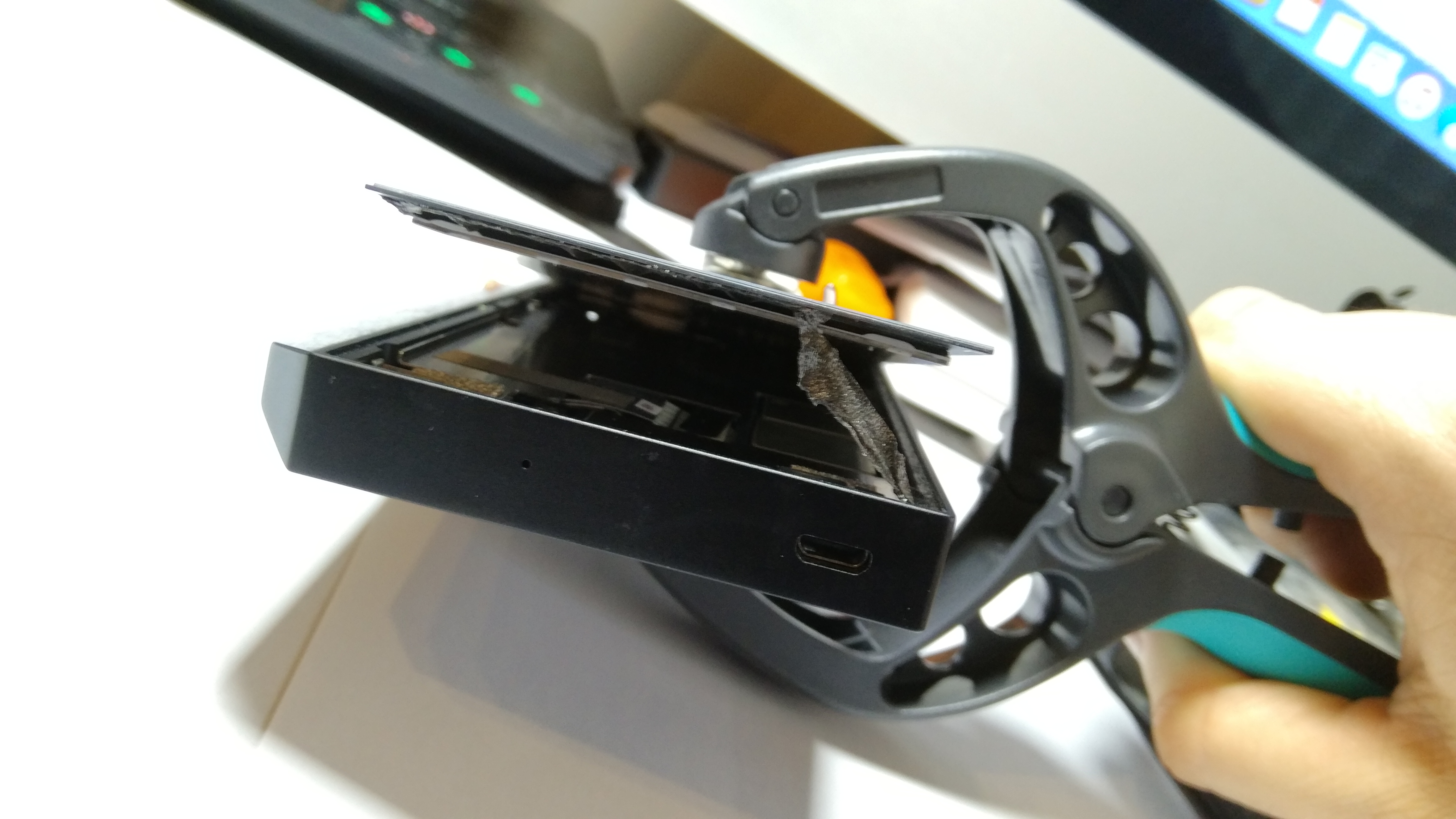
I then used some screen pliers to lift the bottom of the screen a little bit, just enough so I could get a small guitar pick type pryer in. It is imperative that you start at the bottom as there are two ribbons that attach the screen the PCB. You'll see below. This was after I loosened the bottom with the pick.
You'll see the glue on the pic below. It's the double sided tape type - not liquid!
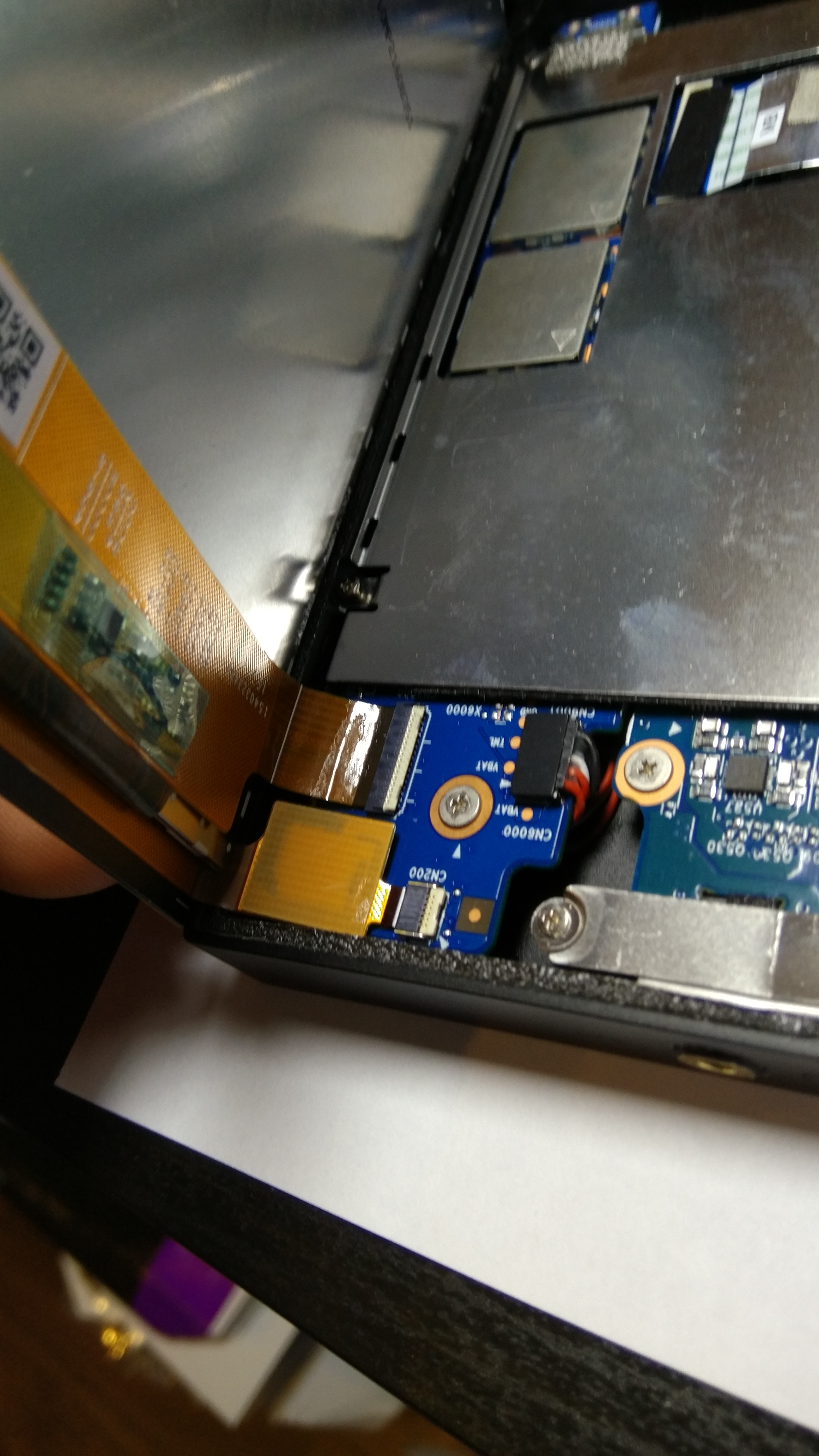
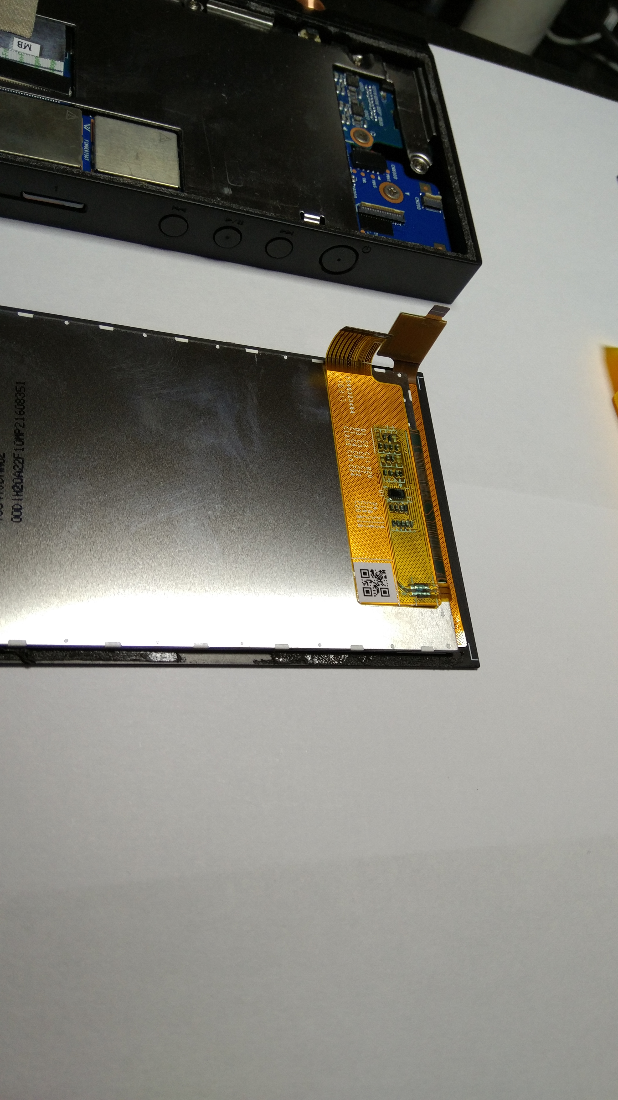
At this point you work your way with the pick to the top right hand corner, being very careful of the ribbons, you'll see them if you look up from the bottom as you go. The below image is looking from the top of the device and the ribbons are on the bottom left of the picture. You'll need to remove the little black sticky protective pads to expose the connector. I used some small tweezers.
Like this (sorry it's not in focus):
You need to lift the back of the white part of the connector to release the ribbon - you'll see in later picture's where it's a bit more in focus.
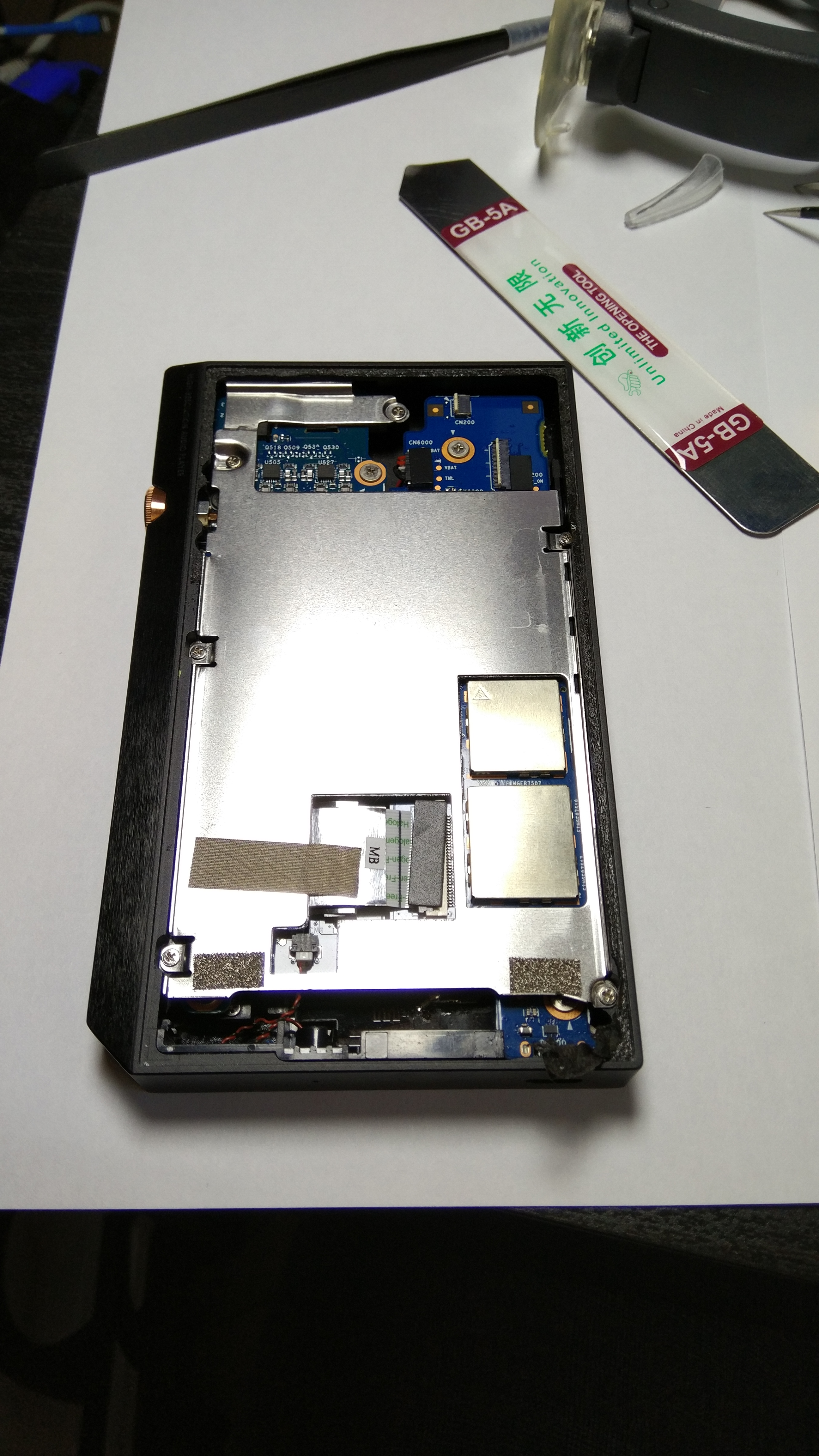
Next you need to remove the silver frame with a small philips screwdriver; there are 6 screws in total, seen below. You need to remove the sticky protective strip - it runs into the middle of the unit next to the sticker that says MB and is grey. I recommend removing it from the metal frame first because it's attached to the ribbon connecting the DAC.
Note, I didn't use the metal pry bar above, it was just taken out of the box.
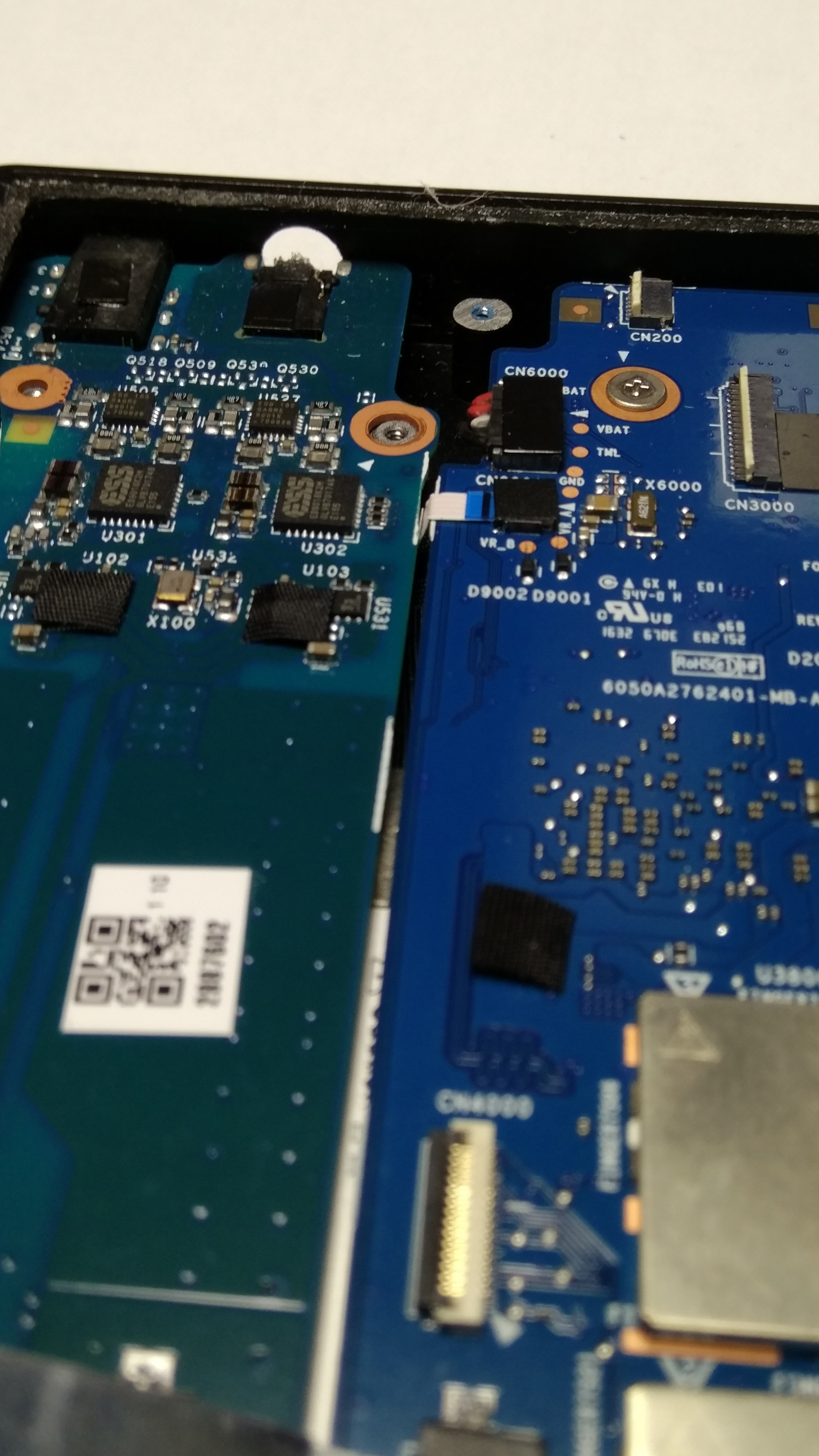
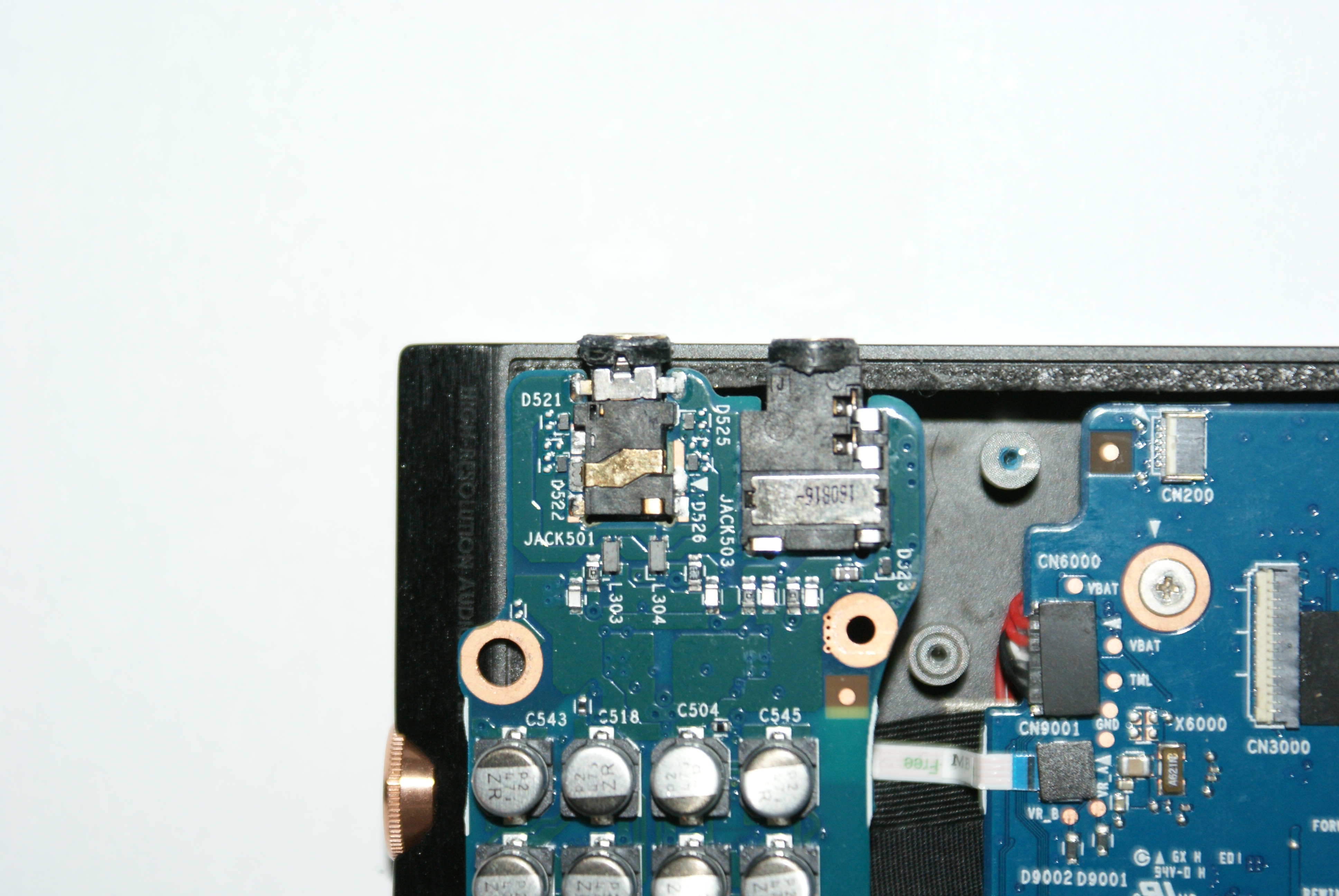
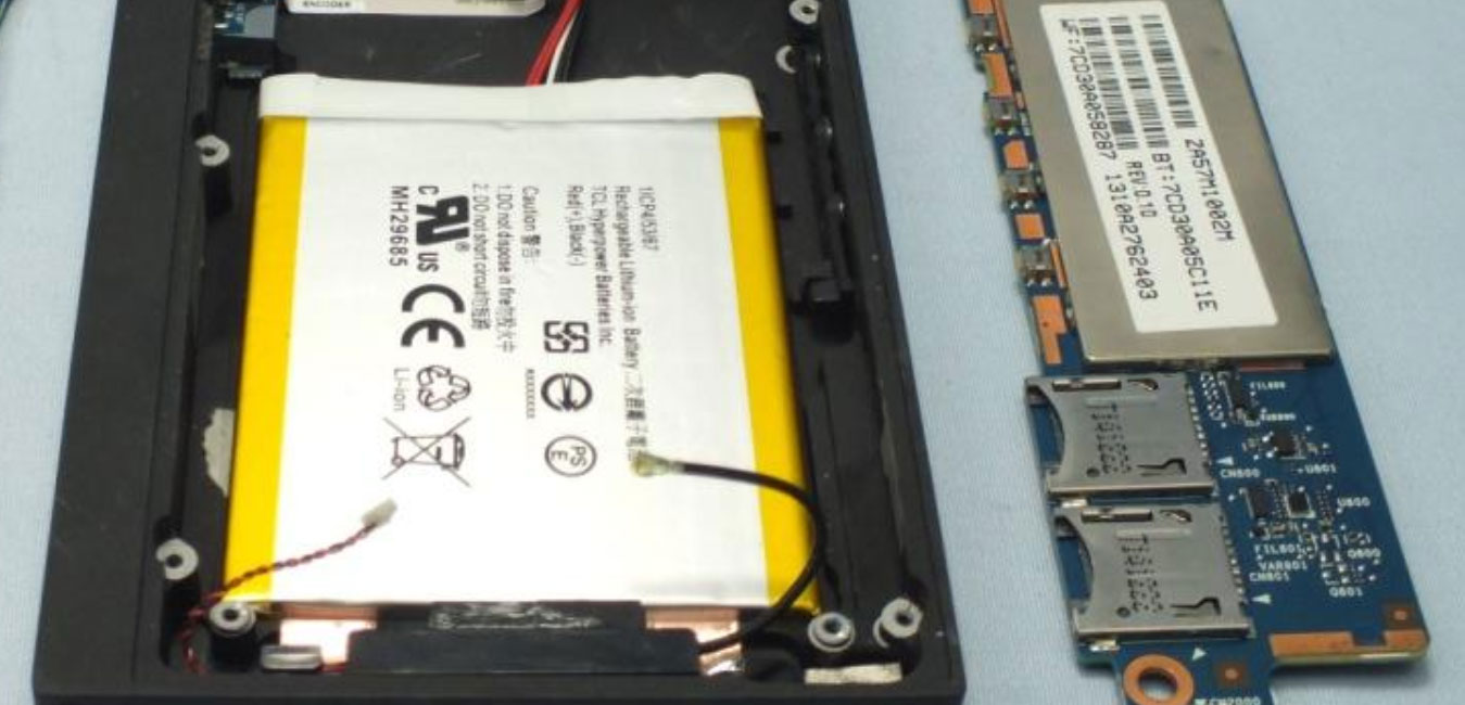
Once removed you'll see both the DAC/Amp and CPU board. The top left are the offending jacks!
There are two Philips screws holding the board in place that need removed. I also removed the snapped jack, which was probably the most difficult because I had super glued it in!
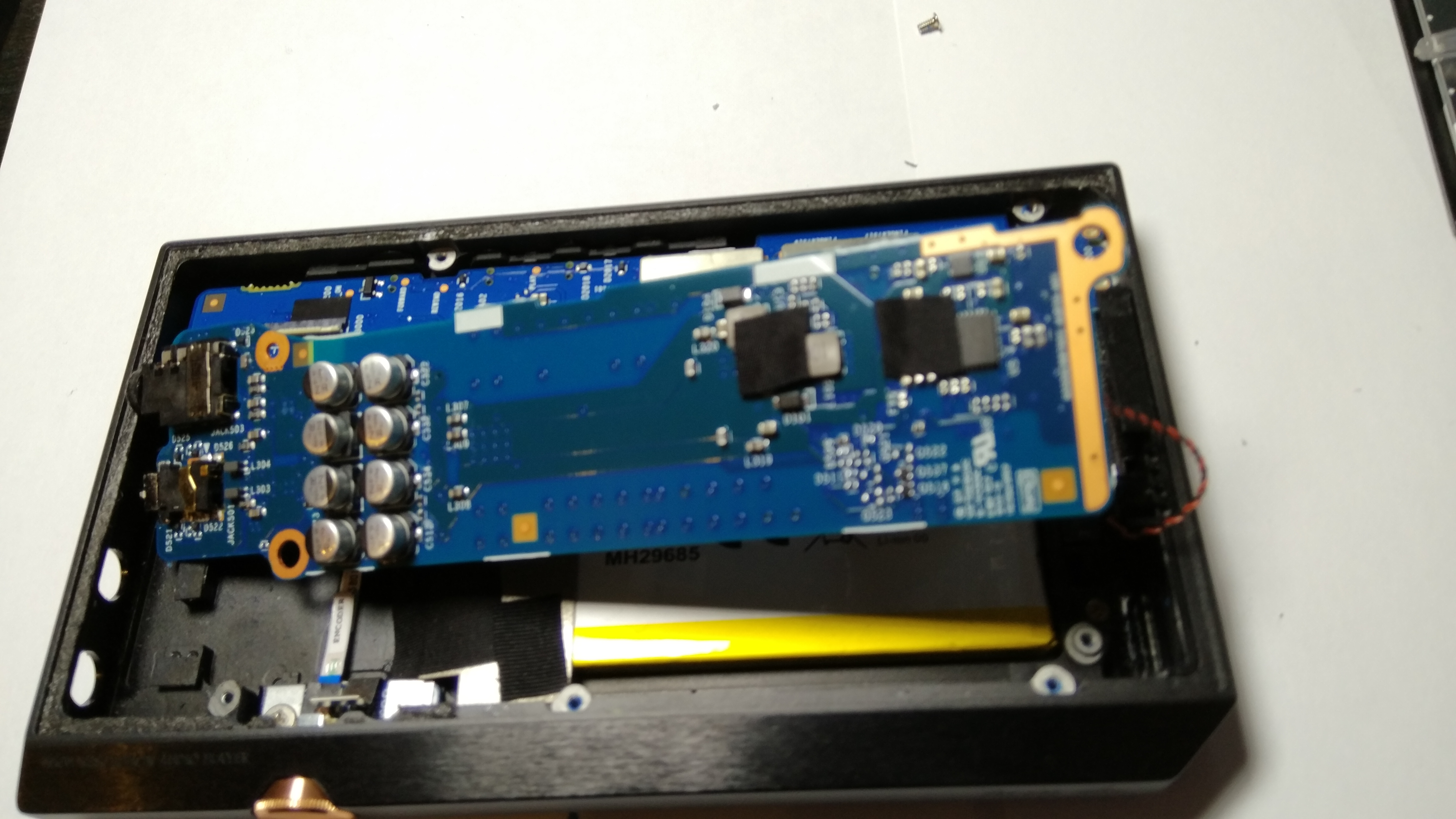
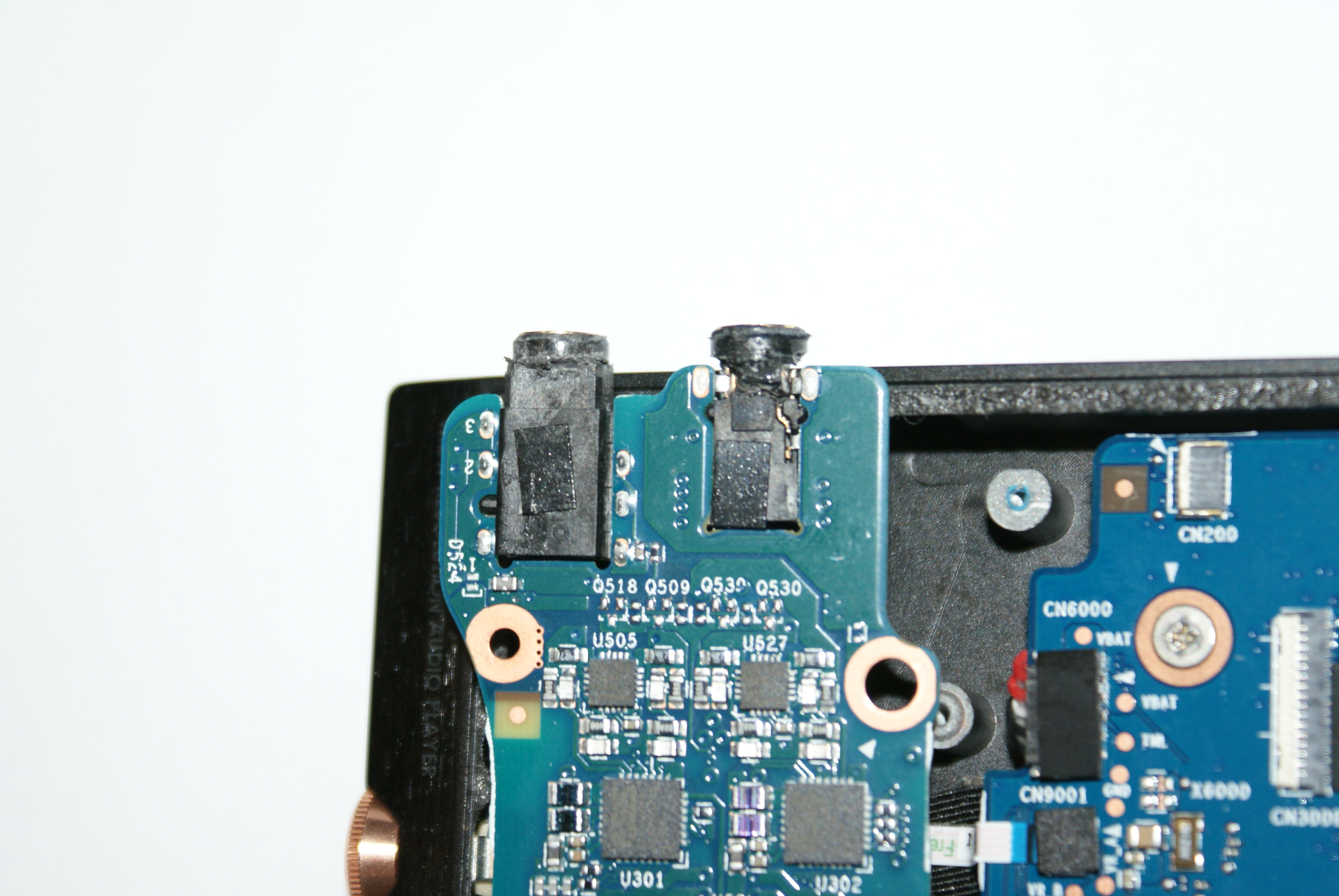
Once both jacks are free of glue you can, very carefully pull it towards the bottom of the unit to clear the holes in the case and then pull it over to the right. You need to be careful of the capacitors on the top of the DAC/Amp. They're to the left of this next picture, about in line with the volume knob.
You also need to be careful of the wiring for the reset button which is red and black twisted rusher and of the ribbon from the DAC/Amp.
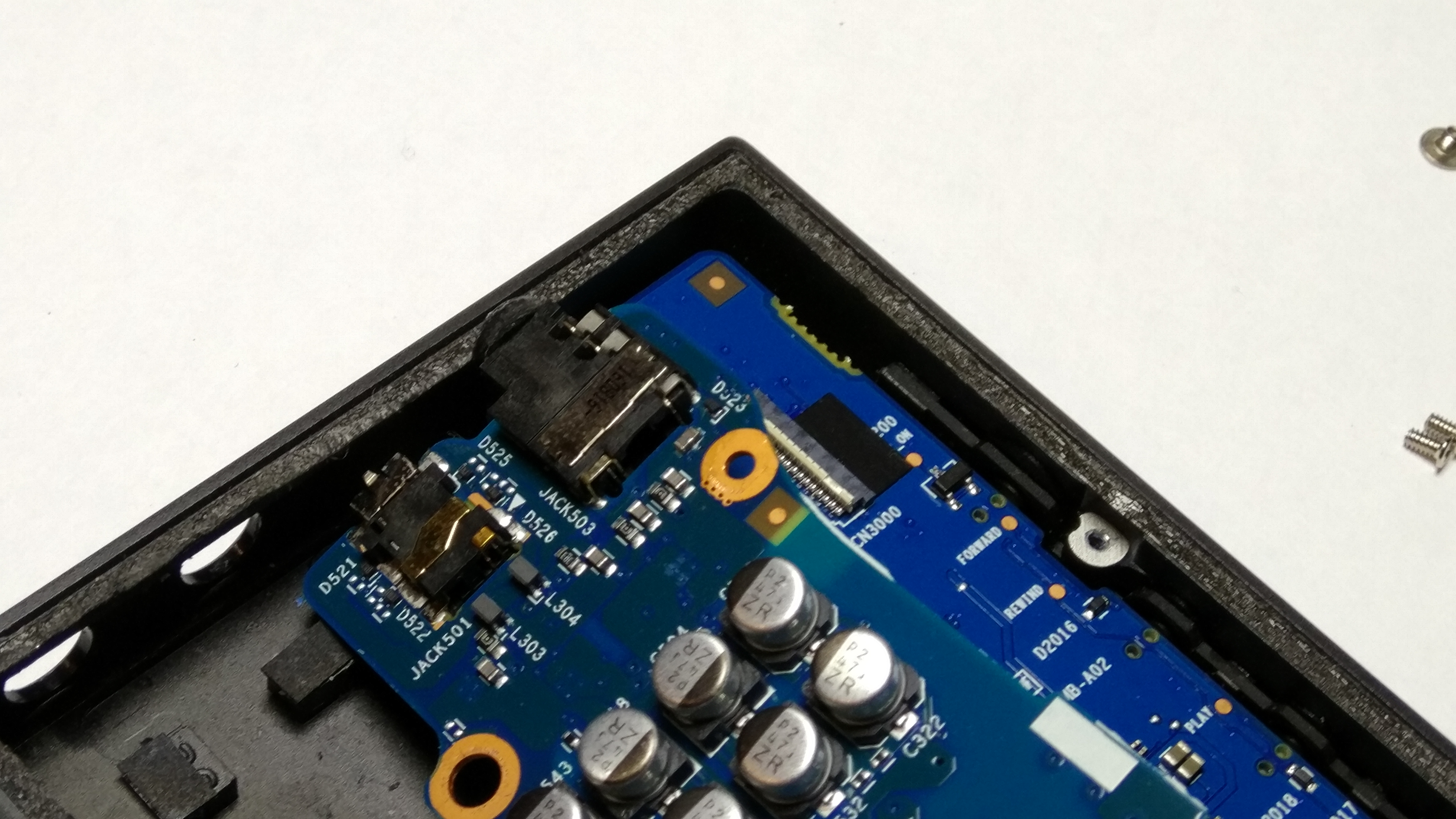
This is the underside of the jacks, where they are soldered into the board.
This is as far as I could get tonight. I need to source some replacement jacks, which may be trial and error to be honest, and then come up with some sort of permanent fix. I suspect it will involve bonding them from the inside - to the inside of the case.
I'll update once I make some more progress.
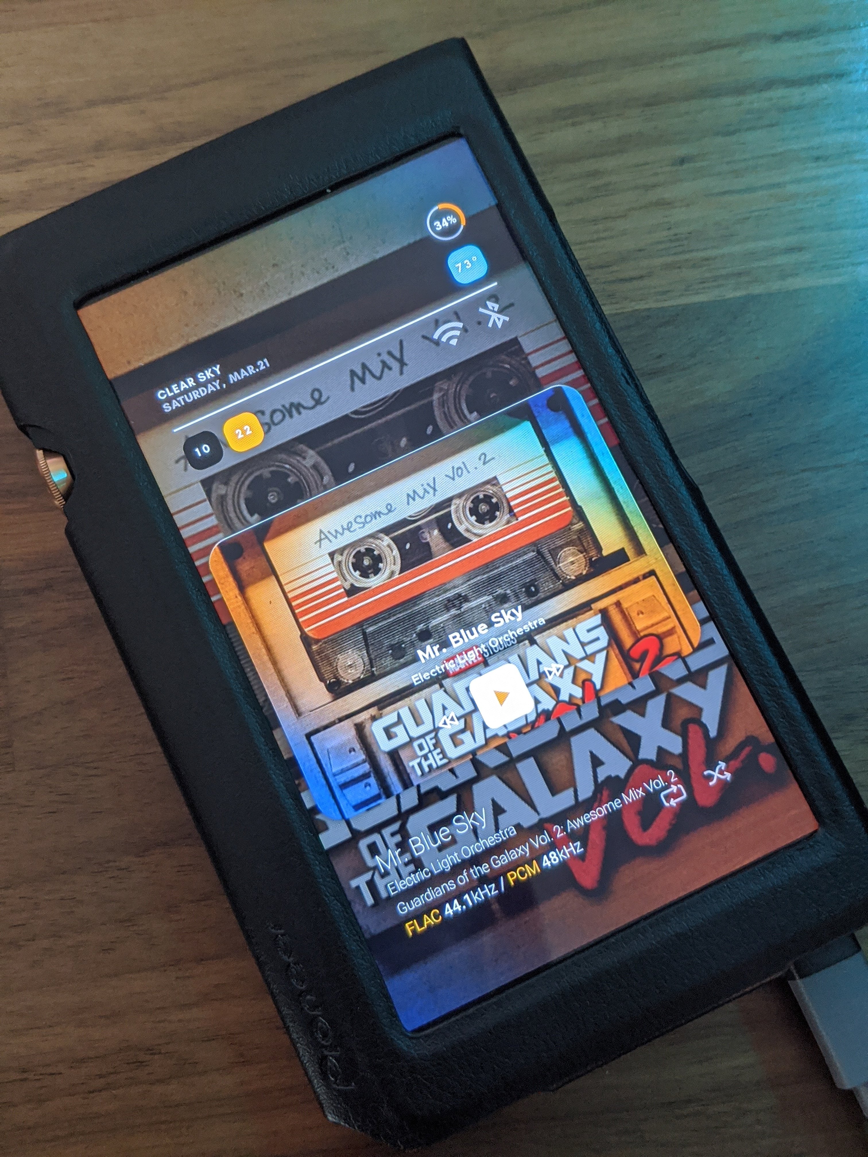
Unfortunately it's now in an array of ziplock bags in a box so I have to use my phone to listen to Tidal!
John


")