Quote:
Originally Posted by cms5423 /img/forum/go_quote.gif
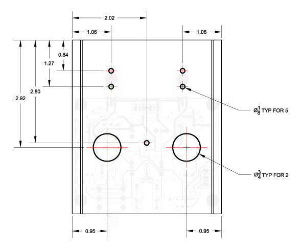
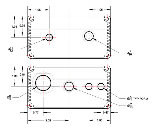
In case this could help someone with the build:
So when you were saying put 50k input resistors on my starving student, were you referring to doing that with a 10k pot or a 50k pot?
Also, I've seen people's upgraded schematics and BOMs that use bypass caps. Are these just caps placed in parallel to the cap that is already there? Like a .22 parallel to c3 and c5, or are they placed befor c3 and c5 and connect to ground? What exactly do these bypass caps do and what capacitors would these be used for?
Essentially, the input resistors push the high gain inherent in the SSMH's tubes into the last portion of resistance represented by the pot. Let's say you use a 10K pot and 40K input resistance. The total resistance seen by the source feeding the amp would be 50K. However, all volume control would occur in the last 10K of that 50K. This is acceptable for almost all loads using the SSMH, because the basic gain provided by the tubes is 19, whereas typical headphone amp gains range from a low of about 2 to a maximum of 11, in the case of a basic CMoy used to power a 300ohm Senn.
Using a 50K pot with a 50K resistor results in a total of 100K seen by the load, but only the last half of the resistance is variable by the pot. Personally - after trying both - I think the 10K and ~40K input resistance is the best combination.
As for bypass capacitors - electrolytics are slow, lack detail, and often sound outright bad when used directly in the signal path. Directly in the signal path, the small film bypass may actually reach down to 1K and below in the frequencies, so that the electrolytic is essentially passing mid-bass and bass, only. It's actually more complicated than this really, because the speed, ESR, etc. all roll into the combination. There's very little data regarding cap bypassing - it's mostly an artistic type thing, learned through experience. Some cap combinations sound awful, others surprisingly good. Wima's are kind of traditional and have a great track record of bypassing caps - in the signal path and without. So, think of them of as kind of a booster on the large electrolytics, allowing them to operate through the entire frequency scale, without coloration and with plenty of speed and sparkle in the highs and smooth mids. Of course, the film cap all by itself would be the best choice, but very few are in sizes of the 470uf or 680uf as used in the SSMH. If you can even find film caps in that rating, they'd probably each be bigger than the entire amp. So, there you are.
P.S. the film bypasses are in parallel - across the leads of the electrolytic, iow.
Also, all my parts get here tomorrow I think!!
Building starts when UPS arrives

--And if someone could elaborate a little bit on the bypass caps, exactly what are they doing in the circuit, like what parts of the signal and why flow into the bypass caps vs the electrolytics, and how do you determine the value of the bypass caps? Thanks

|
-SIGH- Thanks for posting this, but I would've thought my answer up there was enough.
As I stated, there is no science regarding how bypass caps work. You can attempt to run the corner frequency equation on the output coupling arrangement, for instance, but it's an exercise in futility:
Let's say we have a 300ohm Senn as the load -
0.22uf has a -3dB value at 2411 Hz.
So, you might say that the film cap will pass most of the music to the Senns until it gets to 2KHz and below, then the electrolytic takes over.
However, let's say we have a 32ohm Grado as the load -
0.22uf has a -3dB value at 22,607 Hz.
So, you might say that the film cap is useless for Grado's because it will never predominate below audible frequencies.
Unfortunately, we know this is not true. The speed of the film cap comes into play. It may interact with the music signal much more quickly than the electrolytic, regardless of the cutoff frequency for each cap. However, this is highly variable and depends on the specific film cap and the specific electrolytic. Moreover, there's just as much reason to expect the combination of electrolytic and film cap to act as a single 470.22uf, not as separate caps. Yet, you can put a Black Gate in there (assuming voltage ratings are sufficient) and it will seem as if the Wima never adds anything to the equation.
There is little predictably to any combination except that some bypasses seem to work with more regularity than others. The Wima is one of those. Others may end up sounding lousy. The Wima itself can sound lousy in some scenarios - only trial and error apply.
The same can be said for sizing the bypass. One rule-of-thumb that's sometimes quoted is 10% of the size of the electrolytic. This doesn't hold in the larger sizes, however, otherwise we'd be talking 47uf film caps on the output coupler and those are impractically large and expensive.
So how do we know any of this? Trial and error. In the case of the Starving Student, I can assure you that the latest additions by Dsavitsk have made this into a much better amp. I can specifically state that the BOM as it now stands -
SSMH Bill Of Materials
using a combination of the DigiKey and Mouser components sounds better than any other SSMH I've built:
- 680uf 63V Panasonic FC's (short size)
- 470uf 63V Nichicon KW's as output couplers,
- Wima 0.22uf MKP10's as interstage couplers and output bypasses,
- 10K Alpha with 39K input resistors,
- 220uf 16V Muse ES cathode bypass caps
- Vishay-Dale resistors throughout.
This combination will be "chiseled in stone" as far as I'm concerned.
It's far superior to the other prototype built with Muse FG's on the output and Stackpole carbon film resistors, and 50K pot with 50K input resistors. The other prototype, in turn, is far superior to the standard build with no bypasses, no input resistors, etc.