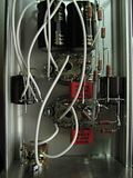
Millett "Starving Student" hybrid amp
May 6, 2009 at 2:25 AM Post #3,091 of 7,277
Quote:

Originally Posted by zkool448 /img/forum/go_quote.gif
If the heatsink is efficient enough, then theoretically the FETs can be mounted directly to the heatsink if you cut two small hole on top of case? (keep case panel/internals cool)
popcorn.gif


No, we're specifically avoiding that. Only a small 1/8" hole is required. The MOSFETs are mounted with Bergquist flow pads on the underside of the case lid, then the heat sinks are attached to the same screw with some heat sink grease between the bottom of the sinks and the top of the case lid. Another screw is added through an 1/8" hole to lock the heat sinks in place and keep them from turning. It's really pretty simple and keeps everything inside. I know no one has had an apparent problem, but 48V is enough to pack a good jolt if one comes into contact with it under the right circumstances. The PCB may introduce a lot more people with less experience to the SSMH. After all, building one P2P sort of requires you to think about these things anyway. On the other hand, a PCB is sort of paint-by-numbers and allows people to relax more than they should, perhaps.
wink.gif


Quote:

Originally Posted by JamesL
Hey, I haven't been on head-fi on a while, but I picked up on this project yesterday -
This was my first P2P, and also my first tube project, so it was a big relief when nothing blew up. I haven't yet hooked up any audio, but the tubes are giving off a nice glow.

I'm a little worried about the capacitors though.
The aluminum case itself gets pretty hot because the heatsinks are cold-welded directly onto it. The capacitors were glued directly onto the case.
Would this be alright? The Muse KZ and pana PW's I think are both rated at 85 degrees


This is just my own opinion, but you might want to get them detached from the case if you can. They'll definitely reach a much higher temperature than "free-floating" if the heat sinks are attached to the case. There's basically just liquid in many of these caps, anyway.

Quote:

Originally Posted by tamasic1
Quote:

Originally Posted by tomb /img/forum/go_quote.gif
And what heat sinks are you using?


http://bellsouthpwp2.net/k/a/karlet/MySSHA.jpg


Well, those look plenty big to me. Again, those temps you measured are not outside of normal for MOSFETs - they can get hotter, for sure. You may even find that things will cool down a bit if you case it up. MOSFETs have a positive temperature coefficient, so they may cool slightly when cased up.
wink.gif
 
May 6, 2009 at 2:19 PM Post #3,095 of 7,277
Quote:

Originally Posted by tomb /img/forum/go_quote.gif
This is just my own opinion, but you might want to get them detached from the case if you can. They'll definitely reach a much higher temperature than "free-floating" if the heat sinks are attached to the case. There's basically just liquid in many of these caps, anyway.


Well, I'll certainly see what I can do.
The power caps are small and can hold their own weight, but the output caps are connected to the other components only via the stranded wire, and I'm not sure how to detach it from the case without compromising structural integrity.

If anybody has got any brilliant ideas, it'd be really appreciated.


Also, thanks for the compliment x3
 
May 6, 2009 at 3:04 PM Post #3,096 of 7,277
Quote:

Originally Posted by JamesL /img/forum/go_quote.gif
Well, I'll certainly see what I can do.
The power caps are small and can hold their own weight, but the output caps are connected to the other components only via the stranded wire, and I'm not sure how to detach it from the case without compromising structural integrity.

If anybody has got any brilliant ideas, it'd be really appreciated.


Also, thanks for the compliment x3


Well, I just made a general comment based on preference if you had a choice. If it's an issue on how to keep those caps stable (they are big!), then maybe you could just measure the temperature on the cans after the amp has run awhile. They might be fine, assuming heat rises, they're underneath, and perhaps the heat transfer coefficient of the glue is not so good.
smily_headphones1.gif
I would not push them toward the 85deg.C. rating, though - you want to be well away from that.
 
May 6, 2009 at 3:42 PM Post #3,097 of 7,277
Quote:

Originally Posted by tomb /img/forum/go_quote.gif
Well, I just made a general comment based on preference if you had a choice. If it's an issue on how to keep those caps stable (they are big!), then maybe you could just measure the temperature on the cans after the amp has run awhile. They might be fine, assuming heat rises, they're underneath, and perhaps the heat transfer coefficient of the glue is not so good.
smily_headphones1.gif
I would not push them toward the 85deg.C. rating, though - you want to be well away from that.


Thanks, but I think you were right. The thermal conductivity of the epoxy I used seems to be fairly high, and I don't know what would happen if the capacitors failed(any dc voltage might go straight through to the headphones)

I removed the capacitor from the case though, and it doesn't seem to be moving around much at all, contrary to what I thought.
The entire amplifier(even the volume knob) seems to be running fairly hot, so I'm trying my best to dissipate heat anywhere I can.
 
May 6, 2009 at 6:40 PM Post #3,098 of 7,277
update:
I wish I could measure the temperature somehow so I know if the temperatures are normal, but subjectively, they're unbearingly hot... and I'm starting to worry that there might be a problem with the FETs.

With 30 minutes uptime, the heatsink and the case feels like the hood of a car that's been parked outside for hours in 100 degree weather.

Is this normal? I'm using 1.5" heatsinks, and the case itself is about 4x2.5x1.5"

I haven't been able to listen to it yet cause I have to order a smaller headphone jack, but if there is something wrong, I might want to order replacement mosfets and maybe the caps as well.

The only things I haven't wired so far are the input and the headphone jack.
 
May 6, 2009 at 10:40 PM Post #3,100 of 7,277
Well my heatsinks are BURNING hot to the touch..which is about 60C..and that's perfectly fine.

**edit*** 64C apparently
smily_headphones1.gif
ignore the dusty case, I am lazy. BTW the amp has been on the entire day so it's as hot as it's going to get.


img4268a.jpg
 
May 6, 2009 at 11:50 PM Post #3,101 of 7,277
Quote:

Originally Posted by tomb /img/forum/go_quote.gif
OK - I had a little trouble with the panel LED (it's still out), but the production board is a success! So are the heat sinks - horizontal mounting using the same screws that attach the MOSFETs and they're barely warm after about an hour. Plus, these heat sinks are cheap as all get out - about $1.30 ea, if memory serves.

I went with a 10K pot, using 39K input resistors - works great and gives close to ~40K input impedance, which should be sufficient for most source coupling caps. It certainly doesn't lack any bass fed from a BantamDAC.
biggrin.gif


SSMH-production.jpg


EDIT: More pics later ...


I'll admit that I'm (mostly) lost when it comes to the electronic theory involved here but I'm wondering about the 10K pot and 39K input resistors you mentioned... Everywhere else I've found in this thread (and the BOM) seems to suggest that the values of the pot and input resistors are the same ... can someone explain???

Thanks,
 
May 7, 2009 at 1:26 AM Post #3,102 of 7,277
Quote:

Originally Posted by sandbasser /img/forum/go_quote.gif
I'll admit that I'm (mostly) lost when it comes to the electronic theory involved here but I'm wondering about the 10K pot and 39K input resistors you mentioned... Everywhere else I've found in this thread (and the BOM) seems to suggest that the values of the pot and input resistors are the same ... can someone explain???

Thanks,


Well, it has to do with understanding the pot is an attenuator that varies input impedance from 0 to whatever the pot rating is. So a 50K pot has an adjustment from 0 to 50K over it's adjustment travel.

In the Starving Student, a bit of a problem is created from two things - the amp naturally has a high gain from the tubes (very high compared to SS standards); second, we try to use a cheap pot in the interests of the "starving student" theme. The trouble is, a cheap pot doesn't necessarily track that well at all positions. Typically, at lower position volume settings, you may get quite an imbalance from one channel to the other. This is pretty irritating when the gain is so high that zero to intolerable volume is only 1/4 to 1/3 the total turn of the volume pot.

So, Dsavitsk came up with the idea of using input resistors. What happens if you use input resistors, the signal sees those as a fixed attenuation first, then sees the adjustable pot. What this means is that if you install a 50K pot and 50K resistors, then the 50K pot adjusts the last 50% of the signal (sort of, but I'm trying to explain in simple terms so I can understand
wink.gif
). So instead of having the entire volume range in the first 1/4 turn, now we have the volume range in the first 1/2 turn.

There are penalties to a certain degree using this arrangement, but they can be overcome with a bit of thought. Ideally, 10K is probably the best for a good headphone amp, because less resistance is in the path of the signal. However, 100K blocks more noise and gives more control. Through empirical knowledge with headphone designs over the last few years, we've all pretty much settled on 50K as a happy medium.

Now - back to the 50K pot with the adjustment over 1/2 turn. If we introduce 100K resistors at the input, then perhaps we get 1 full turn with the same impedance headphone load, the same source strength, and the same 50K pot. However, now we've introduced a total of 150K that the source sees, perhaps 1/3 more than optimum for the ideal amp.

So, if we try a 10K pot, we're back to 1/4 turn unless we use the input resistors. We could try 10K or 20K, but now we've introduced a low enough impedance that the coupling caps on typical DIY-DAC sources are not large enough to overcome the RC bass filtering inherent with a 10K pot and coupling caps on the source. If we go ~40K on some input resistors, then we get two-turn control (if the pot would go that far) over the source volume. However, the total impedance seen by the source is at least 40K, very close to the cultural standard of 50K for most headphone amps.
 
May 7, 2009 at 6:36 AM Post #3,105 of 7,277
Quote:

Originally Posted by zkool448 /img/forum/go_quote.gif
hahaha, same here
wink.gif


TomB, the pot value/design compensates only for those with sensitive/low Z headphones, yes?


Not really. A reasonable gain for many solid-state amps is about 5 - even for Sennheisers. There are instances where you may see gains as high as 11, which is the standard parts gain for a CMoy, I think. However, the 19J6 tubes on the SSMH have a basic amplification factor of 38.
eek.gif


Now, the actual gain is probably not nearly that high in the actual circuit, but even at half that value, you can see that there's a basic issue with gain in the SSMH, regardless of headphone impedance/sensitivity. Of course, with low Z/sensitive phones the effect will be much worse. There's a similar issue with 12AE6 tubes in the Millett Hybrid MAX/MiniMAX, but we use an Alps RK27 in that case, so small volume settings still track very well.

None of this is to say that there's a limitation with the SSMH. The input resistor method works quite well with the little Alpha pot and many successful Starving Students have been built this way, including the Mini Millett sold at Whiplash Audio. As stated before, this method and the use of the inexpensive Alpha pot also preserves the theme of "starving student."
smily_headphones1.gif
 

Users who are viewing this thread

Back
Top