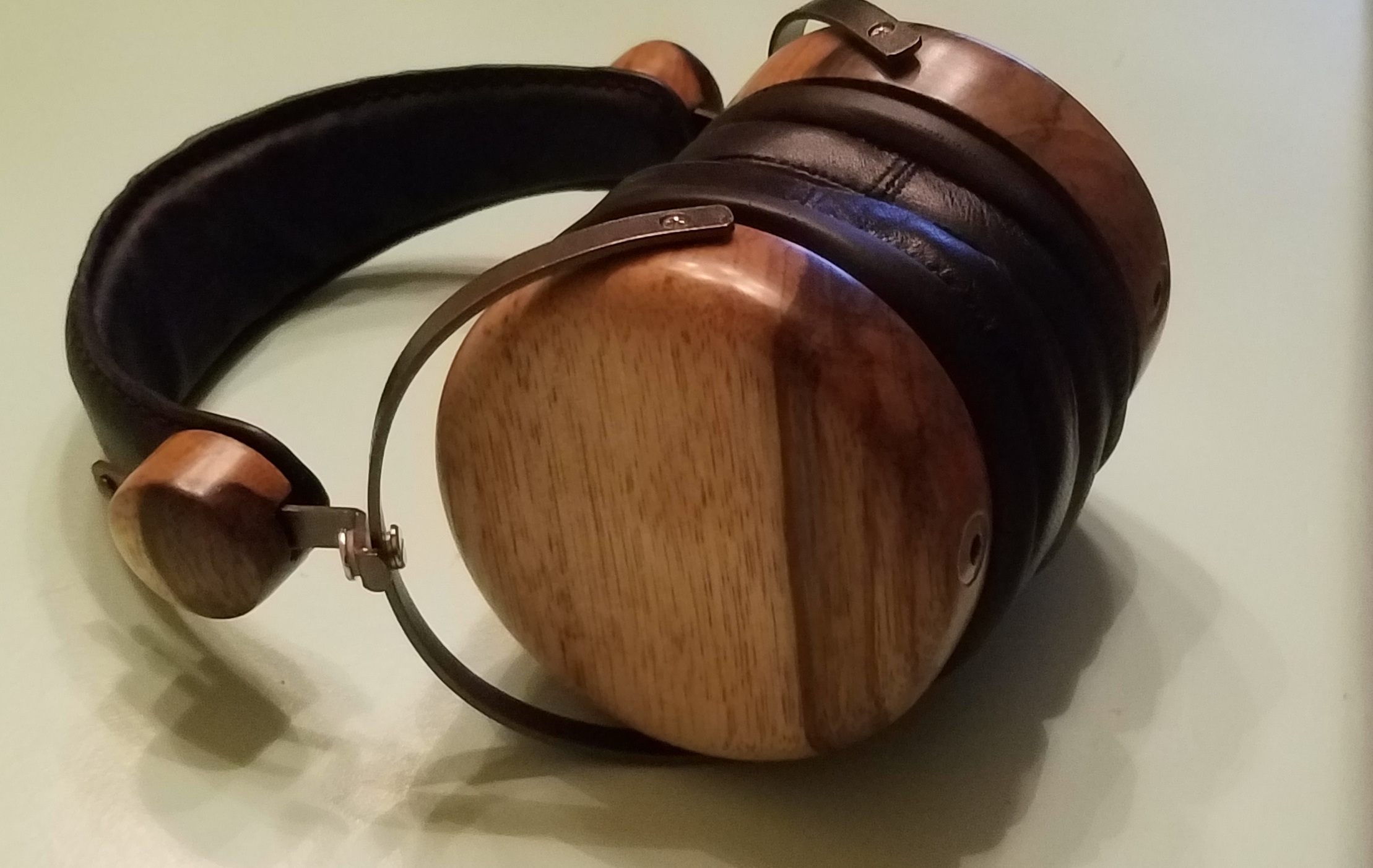
If anyone is performing a cable replacement on these drivers, they'll quickly realize that the solder pads are not the most robust. I used to think the solder pads on Grados were a bit on the sensitive side, but these ... oh, my. In any regard, I've found the "fix" if you run into some issues and think you've "cooked" your driver.
Here's some guidelines to follow for resolving this situation:
1) Using a Ohm meter, connect one lead to one of good the speaker connectors. Then, using the 2nd lead, do some "probing" on the area where the solder pad seems to have dissipated.
2) If you hit a "hot" spot, you'll hear a bit of static through the speaker. This is good - you've found a bit of the speaker lead that you really need.
3) Using some isopropyl rubbing alcohol and a Q-Tip, clean the area where you bad tab currently resides. Hit it a few times with a wet Q-tip and then dry it a few with the dry end of a Q-tip and then slightly dab it dry with a small amount of paper towel.
4) Using a Permatex Rear Window Defroster Repair Kit (about $12.00 at most auto parts stores) take out the small bottle with the tan / brown liquid in it and the small paint brush.
5) Shake the small container of liquid really, really good. If there is still some sediment in the bottom, use a small tooth pick to stir it a bit.
6) With the contents of the container well mixed, "paint" some of the mixture over the area where you found the "hot" spot on the lead with your Ohm Meter.
7) Ideally, about 3 coats of the paint is desired to make a thick "new" adhesive dot for you. The paint is actually a "conductive" paint so applying it will enlarge your pad area for connecting the new wire. Clean the brush with a paper towel soaked in a bit of rubbing alcohol.
8) According to the instructions after you have applied 3 coats, you should let it dry before turning on the defroster. However, the defroster leads are quite a bit hotter than the speaker lead is going to be in your case, so you might not need to let it cure quite as long.
9) With the end of your wire, apply a small amount of super glue towards the end of the insulation and set it into place with the wires covering the new "Painted" pad.
10) Once the super glue has hardened and the wire will no longer move around on you, you can then apply some more paint over the speaker lead and around the new pad, so a connecting bond can be made. You may have to repeat this process 3 or 4 times to get enough paint in place to make that solid bond.
11) Once fully dried, give the terminals another test with the Ohm meter to confirm that you have some static / noise appearing through the speaker again.
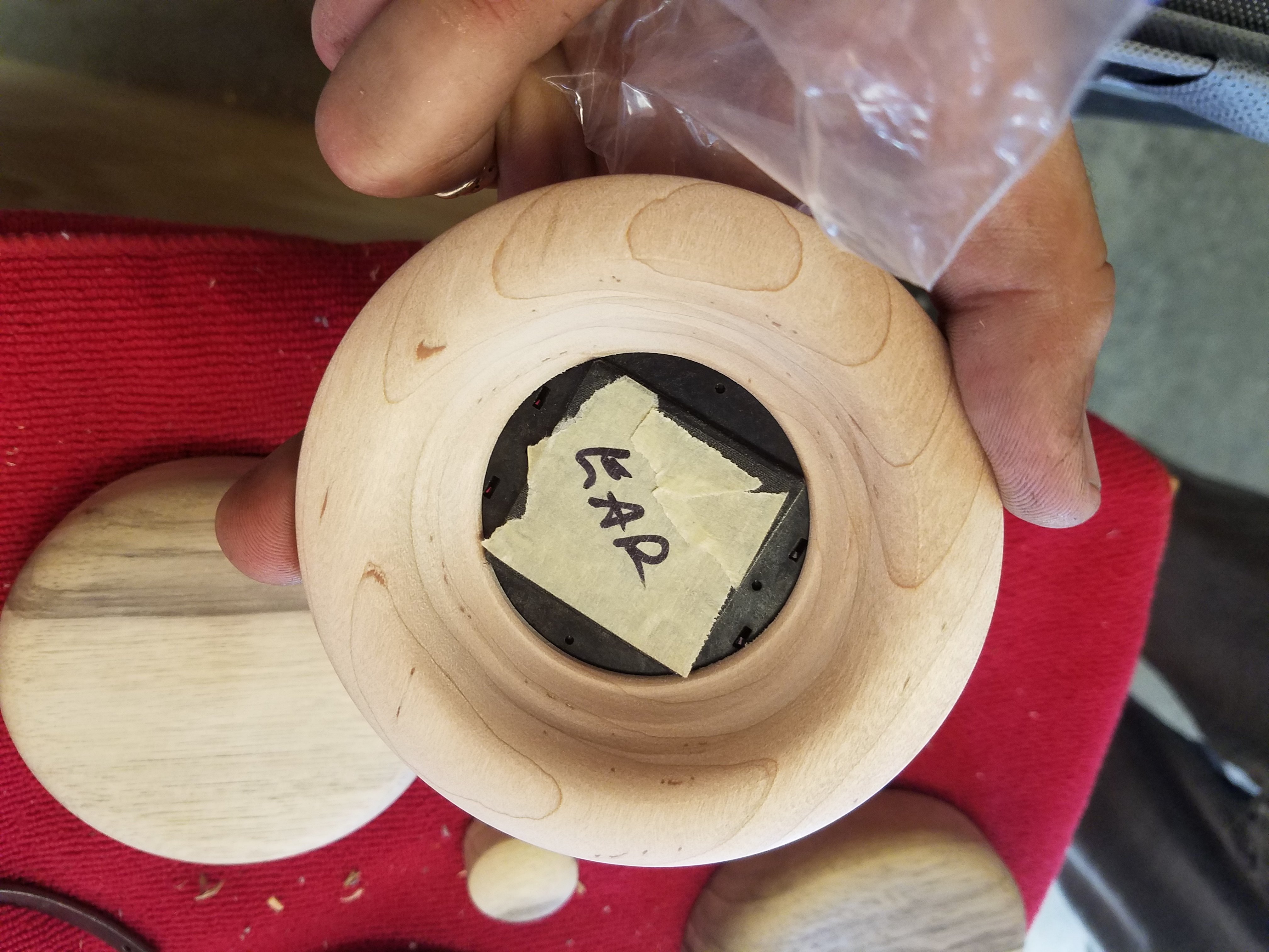
12) Install the baffle into your cup and hold it into place with the 4 screws. Put on the ear pad.
13) Enjoy !!!!
I should say to get to this point, I also tried:
1) Rosin / flux - but the solder was still too squiggly to develop a good bond onto the "hot" spot. Plus, the more I used the soldering iron, the more damage I feared would occur.]
2) Silver solder paste. I was able to acquire a small tube of this past to use in the "hot" spot. However, my iron heated the material too quickly and the results were not too positive for me. But, I'll still hold onto the paste for future soldering "issues" as it may be useful.
Good luck!