Just listened to some Fostex T50RPs today... WOW!
Aug 3, 2016 at 9:33 AM Post #11,296 of 11,345
 
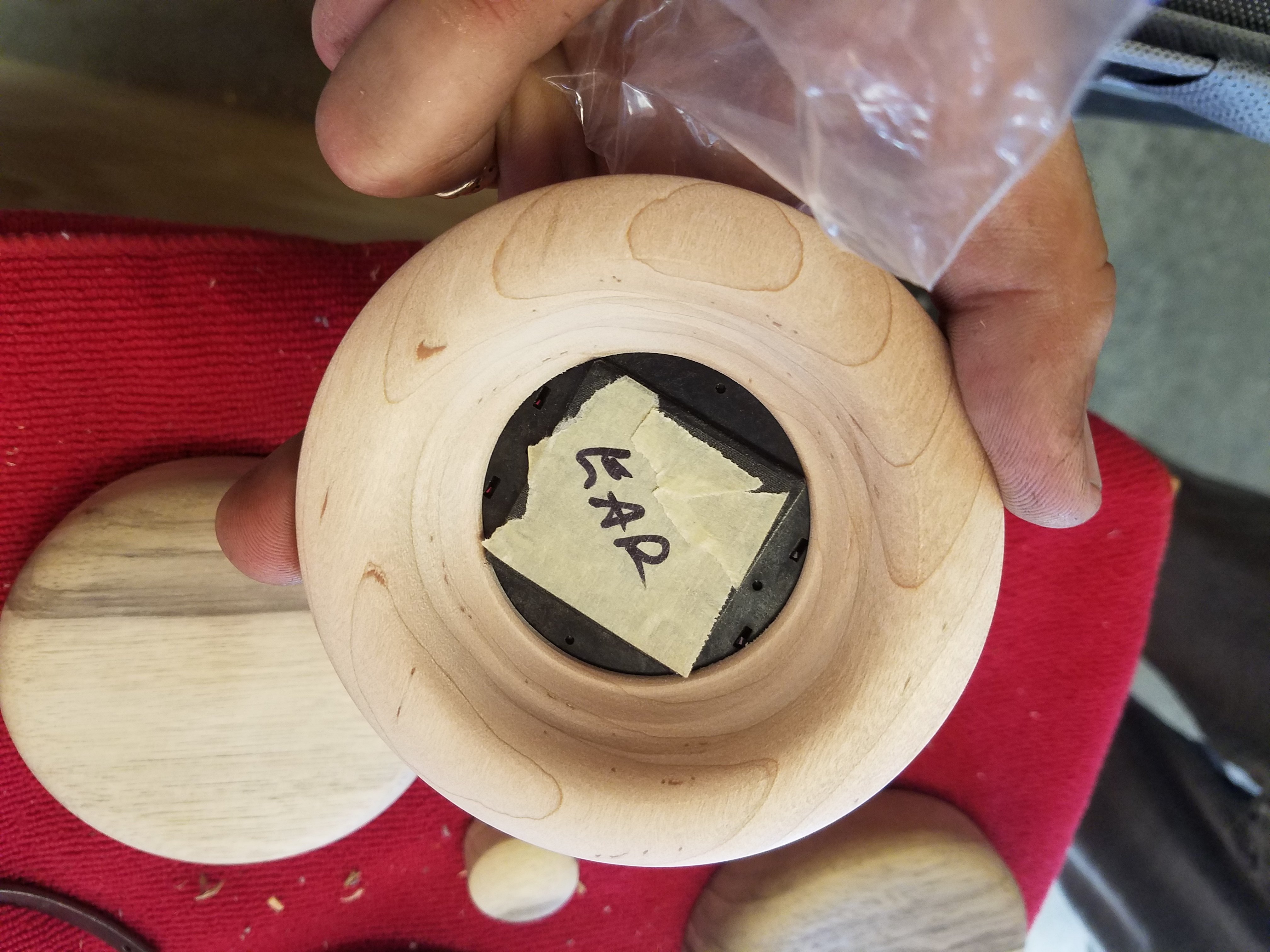
No idea and I've also read some comments here about keeping the driver as stable as possible - something about bolting it to your skull, lol.  And again, if you tighten the baffle all the way it makes direct contact with the cup at the screw holes and around the perimeter.  BMF may be right but that just seems odd to me or maybe he meant something else.
 
The best explanation I can imagine is they're there to stabilize the baffle and driver and reduce any possible vibrations or movement of them.  But I don't really know; I'm far from an expert.
 
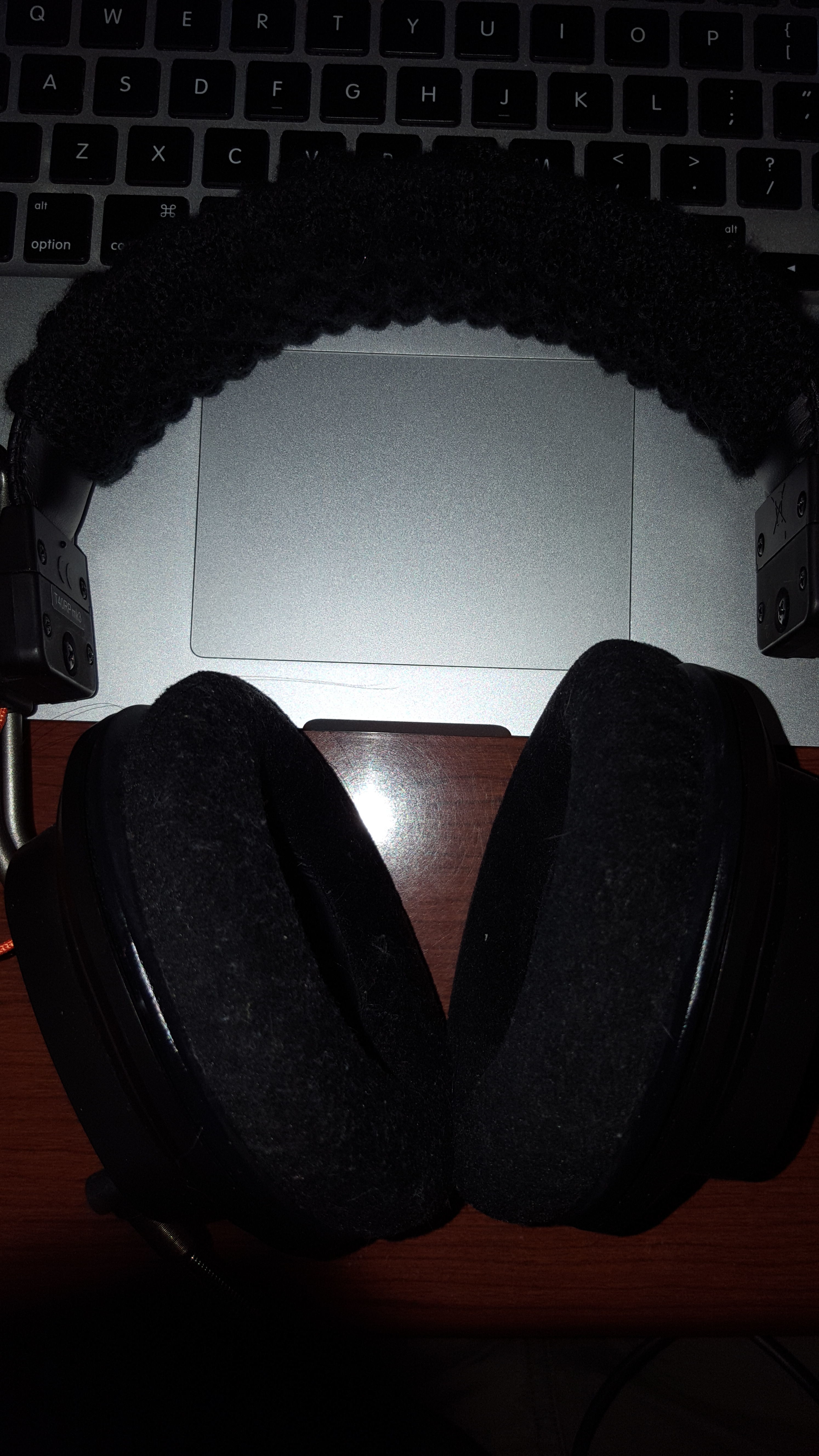
On another note, my T50RPs are not going well.  The HD600 cable is a pain to work because they use a paint to insulate the wires which is difficult to remove and I don't have any heatshrink that small so I have to re-insulate them with electrical tape and hot glue which is messy, they or the t50rp wires don't soak up solder easily, I cracked one of the screw holes, and one of the cables broke off from the driver terminal. 
 
I'm kinda burn't out on them right now and it's really hot here but I'll update more on them when I can.

I have dealt with HD600 wire before and it appears to be Litz wire, it has an enamel coating. The best way to clean it to take solder is with a solder pot but if you do not have one of those just keep the tip of your iron on the wire ends and eventually you can burn off the enamel. Keep applying solder and the rosin flux in the solder will clean the bare wire and allow the solder to stick. Be careful to tin all the wires. The may use similar wire inside the T50RP's but I am absolutely certain about that.
 
Aug 3, 2016 at 4:13 PM Post #11,297 of 11,345
  I have dealt with HD600 wire before and it appears to be Litz wire, it has an enamel coating. The best way to clean it to take solder is with a solder pot but if you do not have one of those just keep the tip of your iron on the wire ends and eventually you can burn off the enamel. Keep applying solder and the rosin flux in the solder will clean the bare wire and allow the solder to stick. Be careful to tin all the wires. The may use similar wire inside the T50RP's but I am absolutely certain about that.


Oh wow, thank you!  I think I ended up getting a good joint in the end but I'll keep this in mind.  I was able to remove most of the enamel by soaking them in Acetone for about an hour but I did notice when soldering that there was some black stuff bubbling up through the solder.
 
I don't think the T50RP wires are coated as they have the typical sleeve insulation but I soaked them anyway.  Although, the white fiber in the T50RP wire was difficult to separate and remove.  Can you just burn that stuff off too?
 
Any tips for soldering directly to the driver terminals?  I've read comments that it's difficult because the stock solder is aluminum and also that the that light plastic coating burns easily. 
 
Aug 3, 2016 at 4:38 PM Post #11,298 of 11,345
Leaving a pigtail of the original wire on the drivers is often the easiest way.
 
Aug 3, 2016 at 4:59 PM Post #11,300 of 11,345
I have not had experience soldering to those pads so I cannot help with that part.
 
Aug 3, 2016 at 6:45 PM Post #11,301 of 11,345
If using a pigtail of the original T50RP wires from the solder pads, use a lot of liquid flux (Kester flux pen) and a hot iron around 700F to tin the original T50RP wires; they don't easily take solder so it may require 2 or 3 tries to get adequate coverage. Make a "hook" by using needle nose pliers at the pigtail and the new wire and crimp in place for a good mechanical joint. Add some heat shrink for insulation where you join your new wires to the pigtails then flux the mechanical joint and apply a bit of solder to make the joint patent. Slide the heat shrink over the soldered joint and finish with a heat gun.
 
If soldering new wires to the T50RP solder pads, add a drop of liquid flux (Kester flux pens work well) and quickly ( 1 or 2 seconds, MAX) add a bit of lead eutectic solder to the pads. Be very careful to Not overheat the solder pads or you may damage them or melt them off the diaphragm. Prepare your new wires with flux and tin the tips. I find that silver coated copper wire tins the easiest. Next, add a drop of liquid flux to the solder pads and to the tinned wires. Position the wire on top of the pad and apply enough downward force to keep the wire in contact with the pad. Tin your iron and touch your iron tip to the pad and the wire for 1 or 2 seconds and then remove the iron. Keep pressure on the wire-to-pad junction until the solder cools and solidifies.  
 
Both methods work for me.
 
Good Luck!
 
Aug 3, 2016 at 11:46 PM Post #11,302 of 11,345
  If using a pigtail of the original T50RP wires from the solder pads, use a lot of liquid flux (Kester flux pen) and a hot iron around 700F to tin the original T50RP wires; they don't easily take solder so it may require 2 or 3 tries to get adequate coverage. Make a "hook" by using needle nose pliers at the pigtail and the new wire and crimp in place for a good mechanical joint. Add some heat shrink for insulation where you join your new wires to the pigtails then flux the mechanical joint and apply a bit of solder to make the joint patent. Slide the heat shrink over the soldered joint and finish with a heat gun.
 
If soldering new wires to the T50RP solder pads, add a drop of liquid flux (Kester flux pens work well) and quickly ( 1 or 2 seconds, MAX) add a bit of lead eutectic solder to the pads. Be very careful to Not overheat the solder pads or you may damage them or melt them off the diaphragm. Prepare your new wires with flux and tin the tips. I find that silver coated copper wire tins the easiest. Next, add a drop of liquid flux to the solder pads and to the tinned wires. Position the wire on top of the pad and apply enough downward force to keep the wire in contact with the pad. Tin your iron and touch your iron tip to the pad and the wire for 1 or 2 seconds and then remove the iron. Keep pressure on the wire-to-pad junction until the solder cools and solidifies.  
 
Both methods work for me.
 
Good Luck!


Thank you, bluemonkeyflyer!  That helps me out a lot.
 
So you're adding solder to the factory solder on the pads?  You're not removing it first?
 
Aug 4, 2016 at 6:32 AM Post #11,303 of 11,345
Don't remove solder from the factory solder pads.

I find that adding a tiny bit of solder to the factory pads makes it easier join the new tinned wire to the pad. I clean my iron, flux the pad, hold the iron and solder near the pad, touch solder to iron, and immediately touch iron to pad for no more than 2 seconds.

I use a fine conical tip at ~ 650F. Using a blunt tip like a chisel or screwdriver tip will hold more heat so the temperatures I use would have to be reduced.

Don't try soldering to the factory pads unless you have good equipment and a lot of soldering experience or you risk destroying the diaphragms.
 
Aug 14, 2016 at 8:06 PM Post #11,304 of 11,345
I wish you guys would make step by step youtube videos how to do a basic overall improved sound mod using the Mayflower mod kit.
 
I bought the mod kit, but there are so many mods its overwhelming and I just can't decide... ugh I just want something simple that does improve soundstage some if possible, if not then just overall sound... don't want to go super hard core... but it seems like that is the only option, ugh.
 
Aug 18, 2016 at 1:45 AM Post #11,305 of 11,345
I had a go at re-soldering the wires to the driver terminal today.  I wasn't happy with my previous job from the HD600 cable to the stock pigtails so I decided to go straight to the driver with the HD600 cable.  I followed your advice, bluemonkeyflyer, and it went really well!  Except they have that dull/cold joint appearance.  Do you think this is a problem?
 
Here is a picture of the end result but it doesn't show off the dull finish of the joint because of the flash.  It's very dull - looks like one of those fishing line sinkers.


Managed it with a 25W Weller pen and a Hakko tip that fits snug over the stock tip.
wink.gif


I also used Paladin79's method of just tinning and burning off the enamel which also worked very well and was much easier.


Aug 18, 2016 at 9:34 AM Post #11,306 of 11,345
  I had a go at re-soldering the wires to the driver terminal today.  I wasn't happy with my previous job from the HD600 cable to the stock pigtails so I decided to go straight to the driver with the HD600 cable.  I followed your advice, bluemonkeyflyer, and it went really well!  Except they have that dull/cold joint appearance.  Do you think this is a problem?
 
Here is a picture of the end result but it doesn't show off the dull finish of the joint because of the flash.  It's very dull - looks like one of those fishing line sinkers.


Managed it with a 25W Weller pen and a Hakko tip that fits snug over the stock tip.
wink.gif


I also used Paladin79's method of just tinning and burning off the enamel which also worked very well and was much easier.


Looks OK. Have you listened to them?  
 
Use a DMM to test resistance between the terminals on each diaphragm. You should get around 47 to 50 ohms and you want Left and Right channels to measure close to the same ohms.
 
If it works and sounds good with no cut-outs, I'd leave well enough alone and not worry about the dull appearance.
 
Aug 18, 2016 at 10:19 AM Post #11,307 of 11,345
   
Looks OK. Have you listened to them?  
 
Use a DMM to test resistance between the terminals on each diaphragm. You should get around 47 to 50 ohms and you want Left and Right channels to measure close to the same ohms.
 
If it works and sounds good with no cut-outs, I'd leave well enough alone and not worry about the dull appearance.

it is good advice to measure between the terminals but I would measure that resistance from the wire end to make sure you have good continuity from that point. Electrically it is the same and should show that same resistance. If you do not get the 47 ohms at wire end, then go to the terminals, if it is fine there, then you know you have a poor solder connection. It is also a good idea to lightly tug the wires you soldered in place, it is better to have them come lose now if they are poor soldered, than later when you seal them up.
 
I should also say that I have not measured the resistance on those diaphragms so I will acquiesce to bluemonkeyflyer's number in this case. Impedance and resistance share the same symbol but they mean different things.
 
As far as dull appearance, the standard 60/40 tin/lead solder that was used for many years would end up nice and shiny when soldered properly, since these headphones are shipped all over the world they would use ROHS (restriction of hazardous substances or some such) compliant solder which can give more of a dull appearance. Since lead is a hazardous substance it is getting to be used less and less.
 
Aug 19, 2016 at 8:41 PM Post #11,308 of 11,345
I got both of the drivers soldered up yesterday.  They both measure 49 to 50 ohms between the pads and also between cable jack and driver pads.  I put them back together and they sound great as well and have very good channel balance, as far as I can tell.
 
Thanks a bunch, guys.  I probably couldn't have done it without your help.
smily_headphones1.gif

 
Now I need to sort the cup screw threads/mounts.  I re-superglued the cracked one but it just opened up again and another stripped again. 
 
I'd really like to find some small threaded metal inserts to fit into the cup screw holes.  I think it could be done.  I'm going to search around and see what I can find.
 
Aug 19, 2016 at 8:54 PM Post #11,309 of 11,345
If you do not find a solution for the cracked screw mount I can probably send you something that will work provided you are in the continental US. You could fill it in and then redrill it or even form a new screw mount if you wanted.
 
Aug 19, 2016 at 9:08 PM Post #11,310 of 11,345
I got both of the drivers soldered up yesterday.  They both measure 49 to 50 ohms between the pads and also between cable jack and driver pads.  I put them back together and they sound great as well and have very good channel balance, as far as I can tell.

Thanks a bunch, guys.  I probably couldn't have done it without your help. :)

Now I need to sort the cup screw threads/mounts.  I re-superglued the cracked one but it just opened up again and another stripped again. 

I'd really like to find some small threaded metal inserts to fit into the cup screw holes.  I think it could be done.  I'm going to search around and see what I can find.


Check McMaster-Carr for inserts.

Check Post #1 of FIMM for info about how to use superglue and a 2mm drill bit to repair stripped cup threads.
 

Users who are viewing this thread

Back
Top