ATH-M50 Removable Cable Mod
Mar 6, 2012 at 11:16 AM Post #80 of 801
Hi guys,
 
I'm new on the forum.
Seems like a nice place, I've been browsing around for the past four to five days and today I registered.
 
First I'd like to say:
 
Thanks for everyone who gave info and pictures on this thread!
You have really helped me a lot! You guys make the world a better place!
biggrin.gif

 
I haven't soldered in years, but when I saw this mod I just had to get at it again.
Bought all I needed yesterday and this morning I cut the main wire of the M50.
Ouch that was a nasty "no going back now sound".
 
With all the helping pictures, text, tips and tricks I was well on my way.
I accidentally broke the red and black audio cable from the circuit board (it was only hanging from the synthetic wire), but I was able to solder them back on luckily.
Should have done the rubber band trick by determinedd.
 
Eventually everything worked out and the result is very nice. Decided to use it as my avatar
tongue.gif

Took me about an hour and a half or something I think, probably longer.
Again, thank you very much!
 
Cheers,
 
 
Daan
 
edit: P.S. I used a regular Zippo lighter to strip the wires, is this a bad idea?
 
Mar 7, 2012 at 2:10 PM Post #81 of 801
Congrats bud, looks very clean, and I hope your headphones still work perfectly! :)
 
Yeah I hear ya on the "omg, if I cut the wire, there's no going back.... (worried face)... SNAP.... o well, too late" :p
 
For me, I just rubbed the wires on the soldering tip to "burn" the insulating coating off them!
 
But as long as you didnt leave the wires in the flames for too long, I thinks that ok! (I've read some ppl doing the same with regular lighters too!)


Quote:
Hi guys,
 
I'm new on the forum.
Seems like a nice place, I've been browsing around for the past four to five days and today I registered.
 
First I'd like to say:
 
Thanks for everyone who gave info and pictures on this thread!
You have really helped me a lot! You guys make the world a better place!
biggrin.gif

 
I haven't soldered in years, but when I saw this mod I just had to get at it again.
Bought all I needed yesterday and this morning I cut the main wire of the M50.
Ouch that was a nasty "no going back now sound".
 
With all the helping pictures, text, tips and tricks I was well on my way.
I accidentally broke the red and black audio cable from the circuit board (it was only hanging from the synthetic wire), but I was able to solder them back on luckily.
Should have done the rubber band trick by determinedd.
 
Eventually everything worked out and the result is very nice. Decided to use it as my avatar
tongue.gif

Took me about an hour and a half or something I think, probably longer.
Again, thank you very much!
 
Cheers,
 
 
Daan
 
edit: P.S. I used a regular Zippo lighter to strip the wires, is this a bad idea?


Mar 21, 2012 at 9:34 PM Post #83 of 801
I know this is old, but I figured I'd post this up here:


Mar 22, 2012 at 7:17 AM Post #84 of 801
hi all, i am interested to mod my headphone to detachable cable like the M50's you guys did here. Just wonder which method is better?
 
1) Solder the wire connected the driver (Replace the original cable without cutting it and reconnect using new cable to the chassis)
2) cut the cable and not touching the connection of the driver. (Using the cut end to connect direct to the chassis)
 
Reason is i do not want to mess up the driver and cable (I am not experience in soldering) and your comments are much appreciated.
 
Mar 22, 2012 at 2:40 PM Post #85 of 801
I would use method number 2 just because you are doing less soldering.  Less soldering/less chance of making mistakes, bridging the connections, or heating up the driver.  If you cut the original cable, you make three solder connections to the chassis, and you're done. 
 
Quote:
hi all, i am interested to mod my headphone to detachable cable like the M50's you guys did here. Just wonder which method is better?
 
1) Solder the wire connected the driver (Replace the original cable without cutting it and reconnect using new cable to the chassis)
2) cut the cable and not touching the connection of the driver. (Using the cut end to connect direct to the chassis)
 
Reason is i do not want to mess up the driver and cable (I am not experience in soldering) and your comments are much appreciated.


Mar 23, 2012 at 9:08 PM Post #87 of 801
Interesting idea, could do that with a clip too
 
Mar 24, 2012 at 9:49 AM Post #88 of 801
Hey guys, speaking on behalf of all the amateurs out there, can someone please post a complete method to perform this procedure (including parts list). I know this may be a bit difficult, but i would really appreciate it, i really want to mod my m50's.
Many thanks !
 
Mar 24, 2012 at 2:57 PM Post #89 of 801
Post #57 has a good picture instruction, 
 
Basically you're going to need a soldering iron (I have a weller soldering gun), solder, solder wick (in case you make a soldering mistake), I used hot glue, and a way to strip the wire (I used the scissors on my swiss army knife), the chassis, http://www.amazon.com/gp/product/B000ML4A2Q/ref=oh_o01_s00_i01_details.  
 
1 Take the pad off, pull around the edges and you will see the lip of the pad, pull it off.
2 There should be four screws holding the cup together, unscrew those.
3 Pull the cups apart carefully you should see the insides of the cup, don't tear the wires.
4 I used my snips to cut the cable from the inside of the cup, just about long enough to reach where the cable is exiting the cup.
5 The strain relief has to be removed.  There is a lip on the inside of the cup that is holding it in by tension.  You need to get this out.
6 There are four screws holding down the driver cover.  Unscrew these.  You will need to snip out a section of the driver cover because it hits the jack.  Put the jack inside the cup and figure out where it hits the driver cover.  I used snips to cut out the section.  I did not cut the cotton ring underneath the driver cover.  Screw the driver cover back on.
7 There are two pegs close to where the cable exits, break off the left peg with pliars, you are doing this to make room for the jack.
8 You will need to carefully strip the big black covering of the cable, there are three wires under there that you will connect to the jack (again I used my swiss army knife).
9  Strip the wires and tin them.  There is white threads that are in the way, this is enamel, you need to burn the coating off with a lighter.  Loop the wire through the holes on the jack (center-black, red-right, green-left).
10 Solder the wires to the chassis, solder the holes closed.
11 Unscrew the top of the chassis ring, put the jack to the hole so the threads are sticking out.
12 screw the ring on the threads, I used superglue and a pair of pliars to get them on all the way.
13 I used hot glue to secure the jack on the inside.
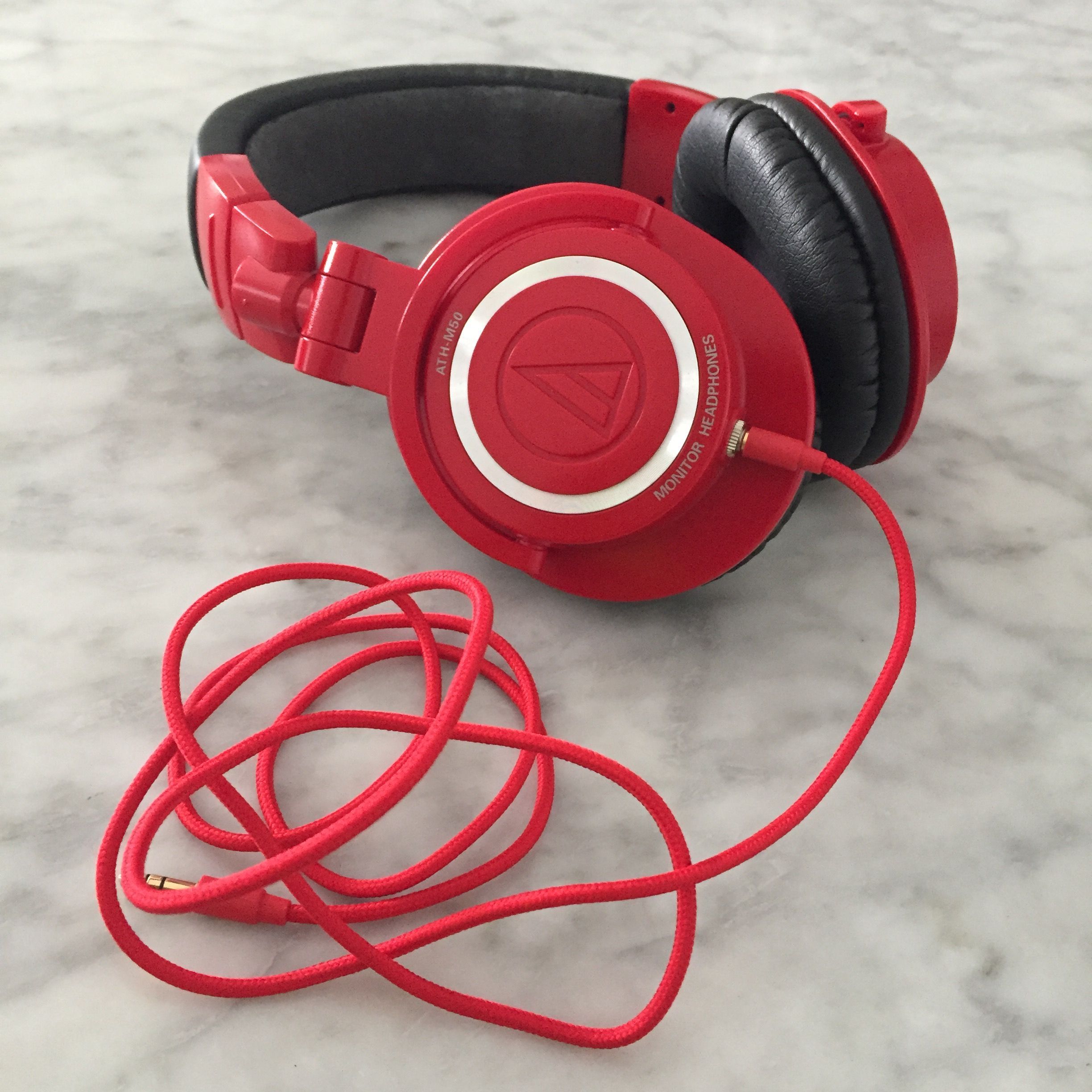
14 close the cup, put the pads on, plug in new cable, and enjoy.
 
I think I got it all if not pm me. 

 
Quote:
Hey guys, speaking on behalf of all the amateurs out there, can someone please post a complete method to perform this procedure (including parts list). I know this may be a bit difficult, but i would really appreciate it, i really want to mod my m50's.
Many thanks !


Mar 24, 2012 at 8:38 PM Post #90 of 801
Thanks so much for the method. :D I'll be looking to order the equipment today. Also i'd like to ask about the part where you cut the cable. So im cutting the cable from the inside, not the outside of the headphone? Because i read somewhere earlier in the post it was the outside of the headphone. Just wanna double check. Thanks :)
 

Users who are viewing this thread

Back
Top