


Sonic Wonder
Member of the Trade: Goldpoint Level Controls
- Joined
- Dec 6, 2010
- Posts
- 44
- Likes
- 12
.
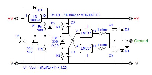
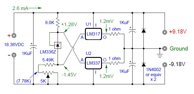
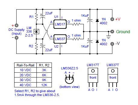
Because those 4 diodes are supposed to have 4 volts across them, not 2.69.
Hmmm - maybe I should run more current through the voltage divider...
")
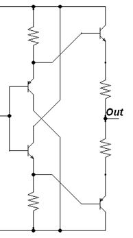
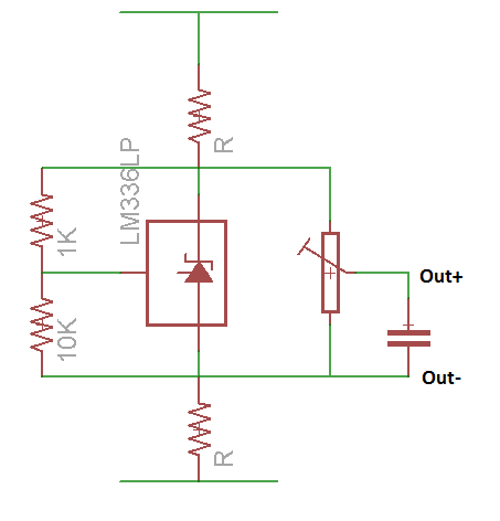
Had a bit of a think about this circuit tonight and have come up with a different approach, still using LM317 & LM337, but using CSSes on the outputs to bias it.
Advantages? Tolerant of variable supply voltages due to CCS design.
Should be pretty good thermal wise, as the performance doesn't depend on the temp-co of the transistors relative to the v-reg, only each to its own complement which should stay pretty close. The CCS current will change with temp, but i don't think that will matter too much for the operation of the circuit.
Resistor values are just pulled from a hat, certainly not optimised, but should give a good idea of the concept.
It seems pretty nifty, and works in a sim but not totally convinced it will go as well in the real world. Maybe with a few tweaks and add in some trimming capability.
https://www.circuitlab.com/circuit/tr4a5y/virtual-ground/
Interesting idea. Care to explain the theory behind it? I don't see what's keeping the output voltages at half the supply voltage.
Yeah I'm a newd, I know. Trying to learn.

Interesting idea. Care to explain the theory behind it?

.gif)
I don't see what's keeping the output voltages at half the supply voltage.
Yeah I'm a newd, I know. Trying to learn.
