Virtual Ground (regulated!) - and Rail Splitter Circuits!

Mar 11, 2013 at 6:54 PM Post #46 of 125
I have thought about using normal diodes, but figured a Zener would be more precise. Turns out I was wrong about the Zener, in the end.
 
Goldpoint, your last design would not work with a varying input voltages. The pot creates an asymmetrical divider.
 
I've been thinking about the last idea by KT88. It makes sense, but it's not really a solution. Datasheets indicate the same 20 mA current requirement up to 12 volt zeners. Also, using a higher zener voltage means you'll limit the voltage range at which the circuit will work. Using a 25 volts zener is simply out of the question, as you'd need 30 V min at the input for it to work properly. 
 
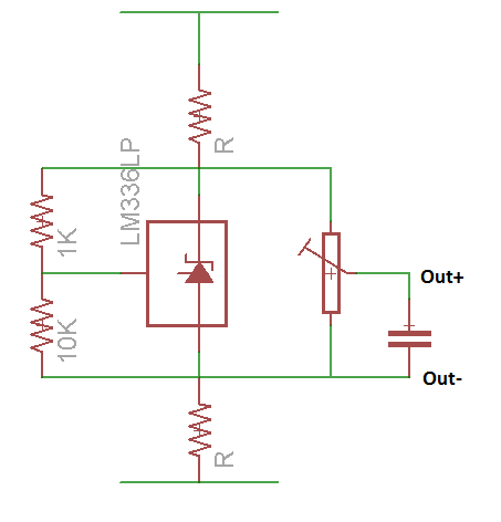
Or did you mean to use an arbitrary voltage zener in a low current voltage divider (<20mA), which will give you a voltage lower than it's rated one, and then adjust that down to the voltage we need using another diver across the zener?
 
It's a step forward, but it's still dependent on input voltage. The next step would be to add a constant current source inside the voltage divider to make sure the zener will always have the same voltage across it, at any given input voltages. I just can't see how you could add a CSS in the divider while keeping it symmetrical. 
 
Mar 12, 2013 at 2:21 AM Post #47 of 125
Hello goldpoint,
I'm aware what you are saying, this is why I've stated that if we are going to use simpler solutions, a trimmer must be added. It's not a luxury, its a must. I merely suggested using tighter tolerance parts so the user won't have to adjust it manually, and since more modern regulators don't require a minimum load of up to 12mA, which is a lot of power wasted. IMO if we don't mind the manual adjustment, the minimum load current required by these regulators is a big issue when using batteries - it can cut battery life in half for some amplifier. For battery use, placing the trimmer in series isn't a good idea because of what I've explained in my last post. For example, if we'd use two 7-cell batteries (for a nominal voltage of 16.8V), and each cell drops by just 100mV we'll have 0.05*0.1*14=70mV of extra voltage across the 1ohm resistors, and that's 35mA of current. Usually the voltage of the batteries will change significantly more than that.
 
KimLaroux, 20mA is a very significant current for a zener. If you'll have a look at the datasheet figures of I/V curves (I'm using the 1N4734A datasheet at the moment just as an example), you'll see a 5.6V zener can work great with just 5mA across it or maybe even less. Its incremental resistance will be a bit higher, but that's probably still about 10-20ohm or so. Its ~50X less than the resistive voltage divider goldpoint posted, so the transfer from the supply voltage to this point will be ~0.001 and even if the batteries drop significantly the change in voltage across it will be very low. This is actually low enough to elevate the need for a constant current biasing scheme in most cases (and probably in our case as well)
 
BTW, using regular diodes like goldpoint did can work (just put them in the opposite polarity). They usually require a much lower current. We must remember there's a lower limit on the current as well, since the LM317/337 have a small current in the adjust pin, so we must make sure its smaller than the current in the resistors in series with the diodes, or the diodes won't operate with sufficient current.
 
Mar 12, 2013 at 3:05 AM Post #49 of 125
That voltage imbalance might be due to not providing enough current to the regulators' adjustment pins. They really want 5-10 mA, and that won't happen with those 10k resistors in the way.
 
Is there a good reason to avoid adding a second 22 uF cap for the positive side of the circuit?
 
Mar 12, 2013 at 3:08 AM Post #50 of 125
How can you change the voltage if the diodes will have a different voltage drop in real life compared to the simulations? Or perhaps the reference of the regulators will vary (it can vary by up to +-50mV). A trimmer is really a must in this case. Even of if the diode could be trusted completely (and we shouldn't do that), just the variance in the regulators internal reference is sufficient to make this circuit waste an extra 10's of mA's of current (the exact value will depend the circuit parameters). And if the reference of the regulators will go in the other directions (towards 1.2 instead of 1.3) the voltage might be too low to conduct appreciable (and required by minimum load of the regulators) current through the diodes.
 
Other than that keep in mind the diodes have an incremental resistance of Vthermal/Idiode, so if we have about 10mA of DC current in the they will be about 3ohms each, so two diodes + 1ohm resistor will be equal to a 7ohm resistor at the output in terms of output impedance. To go to even lower current the resistance will rise (at 3mA it will be about 1+2X9=~20ohm). So in terms of output impedance the diodes should really be kept at the input.
 
tangent, are you sure about the 5-10mA? The datasheet only states 100uA of maximum current for both regulators.
 
Mar 12, 2013 at 9:07 AM Post #52 of 125
Quote:
tangent, are you sure about the 5-10mA? The datasheet only states 100uA of maximum current for both regulators.

 
I'm really talking about the minimum load current. In the standard use of an LM317, you get this with ~120-240 ohms between IN and ADJ. In actual use, this circuit might level out on its own, because there is always current being sunk to ground. But in the simulation, the circuit is idle, thus my guess at the reason for the imbalance.
 
So another way to go at it is to put some dummy resistors across the 470 uF caps, just for purposes of simulation. If it levels out, that's probably why.
 
Mar 12, 2013 at 9:13 AM Post #53 of 125
Yes, the minimum load current can be as high as 12mA to maintain regulation. In the simulation he does have 6mV across the 1ohm resistors so there's 6mA across each of these resistors (going from the LM317 to the LM337).
 
Mar 12, 2013 at 2:16 PM Post #55 of 125

 
As shown simulated including worst case LT1097 input offset -
 
1.4mA total current
 
6 nanovolts output error
 
0R1 ballasts
 
With cheap LM2904 and 1R buffers, 50mV error, 3.4mA
 
Current flows out of an LM317 adj, btw.
 
 
popcorn.gif

 
w
 
Mar 12, 2013 at 4:34 PM Post #57 of 125
I was just hoping the offset was essentially a simulation error, the sort where you've lied to the simulator by not giving it all the real-world conditions, so it lies back at you in revenge. I don't think the 0.13 V of error is worth fixing, if it costs a trim pot. Those can be more expensive than the ICs!
 
I don't see why Iq went down when the divider resistance went down. You had 6.4 mA Iq with 20k across the rails last night, and now you've got 5.2 mA Iq with ~4k across the rails. I see other circuit changes, but I don't see why they'd change Iq.
 
Mar 12, 2013 at 4:43 PM Post #58 of 125
The trimpot is a must in such a circuit so the second option would be best. However, this circuit still fails to address one very important issue, and that's thermal stability. A silicone diode has about -2mV/C tempco, so a 10C rise in the temperature (and this can easily be the difference between running the amp at noon or at the evening) will lower the drop across the diodes by 4*2*10=80mV. Than you have an extra 40mA of DC current at the output. If the temperature drops down instead of going up, the circuit will simply stop working at all.
 
I still think that if diodes are what we want to use a better approach would be using a 5-6V zener diode which has a very low tempco (this is the sweet spot of zener voltage for low tempco), and adding the trimmer in parallel to allow initial adjustment. I've posted it in the last page:

It uses an extra 2 resistors, but it only has a single zener instead of 4 diodes - so in terms of parts count its about the same. The tempco of the regulators is much much lower than that of the diodes and therefore isn't the limiting factor in this case. The zener does require a few extra mA's, but its worth it since it can save 10 times as much at the output under different operating conditions.
 
tangent, regarding the current. Now the resistors (1ohm) only have 2mV across them so that's 2mA, in the previous simulation they had 6mV so 6mA. That's the cause for the difference between the simulations.
 
Mar 12, 2013 at 5:04 PM Post #59 of 125
Don't you like the simplicity of this circuit, it's low cost and the common jellybean parts though? I am going to hook it up to my headphone amp this afternoon for a real-world listening test. Hmmm - maybe I should run more current through the voltage divider...
 
 
Mar 12, 2013 at 7:20 PM Post #60 of 125
Quote:
Don't you like the simplicity of this circuit, it's low cost and the common jellybean parts though? I am going to hook it up to my headphone amp this afternoon for a real-world listening test. Hmmm - maybe I should run more current through the voltage divider...


How's this even working? It's not supposed to work. Are you simulating these or testing them using real components?
 

Users who are viewing this thread

Back
Top