Virtual Ground (regulated!) - and Rail Splitter Circuits!

Mar 9, 2013 at 6:48 PM Post #17 of 125
Quote:
I actually tried that circuit. It seems to work when you have a very small load.
 
If your load is connected to the virtual ground and the negative rail, it will work correctly.
In that case it works just like a regular positive voltage regulator circuit - up to the current
(amperage) limits of the LM317 regulator.
 
But if you connect a load from the positive rail to the virtual ground, the ground point will
actual move - it will be pulled upwards the positive rail as the load increases. see?
 
You need both regulators there to "hold the virtual ground point steady" - to keep it from "moving".

 
This is what I explained in my last post. It's relevant to using fixed regulators. My design doesn't work the same way, so this is not a problem. With my design, the ground will always be halfway between the rails.
 
The sink and source difference is a valid point. An LM317 probably isn't designed to sink much current. Where can it even sink it to anyways? The only return path I see is the adjust pin... It's not like it can sink an Amp trough there. This would seem to dictate the use of both complementary regulators. The LM337 would "source" the current used by the V+ rail, and the LM317 "source" the current needed by the V- rail.
 
Mar 9, 2013 at 6:57 PM Post #18 of 125
Quote:
Have I misread you design at first? (I hope so)
 
Are you saying that the LM317, for instance, will output +1/2 of the rail-to rail voltage (not zero volts in reference to the positive rail)
and that the LM337 will output -1/2 of the rail-to-rail voltage (not zero volts in reference to the negative rail)?
 
If so, you DID do it. We've GOT to breadboard this circuit...

 
The LM317 outputs half of the difference between V+ and V-.
The LM337 outputs half of the difference between V- and V+.
 
Those two outputs are, in theory, at the same point : half of the rail-to-rail voltage.
 
It, in theory, works with any supply voltage between 4 and 40 V.
 
I would have breadboarded it already if I had the parts. 
biggrin.gif

 
Mar 9, 2013 at 7:31 PM Post #19 of 125
Quote:
I actually tried that circuit. It seems to work when you have a very small load.
 
If your load is connected to the virtual ground and the negative rail, it will work correctly.
In that case it works just like a regular positive voltage regulator circuit - up to the current
(amperage) limits of the LM317 regulator.
 
But if you connect a load from the positive rail to the virtual ground, the ground point will
actual move - it will be pulled upwards the positive rail as the load increases. see?
 
You need both regulators there to "hold the virtual ground point steady" - to keep it from "moving".
(One does it in one direction and one in the other direction, so to speak.)
 
But there are substantial advantages virtual grounds at times - and no reason not to use them
if they are properly designed.

 
No I don't see. It doesn't sound at all likely to me. You obviously did not monitor the ground-to-opposite rail voltages when you did the tests. If the ground point moves toward the positive rail, the negative rail must move toward the positive rail by double the amount, because the 2 resistors and the zener diode keep the regulator adj. pin at 1.25V negative of the centre point, and its output therefore at the centre point.
 
As Kim said, the 2 outputs should be at the same voltage. This is regardless of loading, otherwise the circuit is not working. Therefore only one of them is needed. Think about it.
 
You built the original circuit with symmetrical regulators because your gut instinct told you to do it. Very often, however, in electronics our gut instincts betray us.
 
It's simply untrue that there are substantial advantages to virtual grounds at all times, as you will find if you research the subject more fully.
 
Mar 9, 2013 at 8:08 PM Post #20 of 125
Um, you need to bench test what you're talking about. I did bench test it, and I'm telling you, you cannot use only ONE regulator (positive OR negative) to make a proper virtual ground. Will not workie right. I mean: TRY IT YOURSELF. YOU hook it up and load the top and/or the bottom respectively. You will see what we are saying is true. There is nothing wrong with virtual grounds if designed correctly! (Really) Have a nice day. Wishing you luck.
 
 
Mar 9, 2013 at 8:09 PM Post #21 of 125
I think he didn't test your circuit, but his with only one regulator - a fixed regulator. In which case his results confirm what I theorized in my post before his. You can't do this with a single fixed regulator.
 
Wakibaki, there's a thing I don't understand about using only the LM317:
 
In this design, the LM317 sources current to gnd and the current flow back trough V-. This is what the LM317 was designed for.
 
But if you have no load on the V- rail, and a load on the V+ rail, then the current flows out of V+, back into Gnd... and where? The LM317 has no way to sink the current back to V-.  So how would it work?
 
Mar 9, 2013 at 9:45 PM Post #23 of 125
Good question Kim, I should have paid more attention.
 
We're not dealing with DC here, we're dealing with AC. As long as the the net current is zero there will be no problem, there are some big caps there. What I should have thought of, and which is why he is getting the result he does, is what happens at DC. If there is a net DC bias that exceeds the leakage through the caps and the adj. pin there could be a problem. 
 
Sorry goldpoint, your point is well taken, and probably the simplest solution is to use 2 regulators. You are mistaken about virtual grounds in general, however.
 
w
 
Mar 9, 2013 at 9:52 PM Post #24 of 125
Quote:
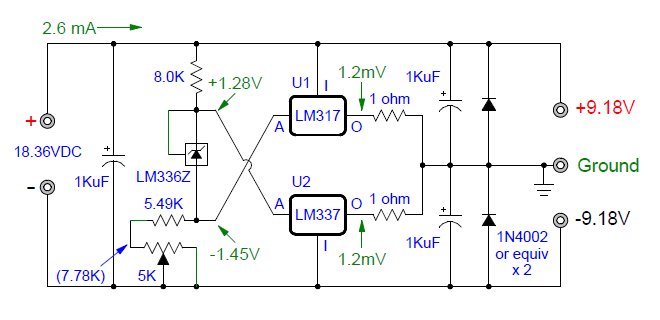
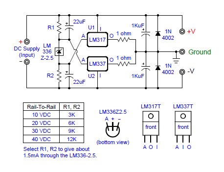
WOW! SUCCESS! This does sort of work you guys. The only problem so far is that even with 10 ohm output resistors, the circuit still draws quite a bit of juice (54mA), making it not ready for prime time battery use yet.
 
 
So this was a quick test circuit. (circuit above)  You can see the output voltages, relative to the virtual ground, are not exactly equal. However, they are "close enough for government" work, like we used to say... It's alive!  A rail splitter virtual ground using two, common, inexpensive adjustable regulators! When we get the quiescent current down to nearly zero - then we will BE there!

 
I've been thinking about all these problems.
 
It's not designed for portable use that's for sure. I don't think it would be reasonable to even try to use such a device for portable use. And just to be clear, I'm of the opinion that for desktop use, there's very little reasons not to use a proper dual supply with a center-tapped transformer. ;)
 
Since it's unregulated, you'd have to regulate each rails separately after the rail splitter. This would take care of unequal voltages between the rails and noise introduced by the zener (if any).
 
Have you tried the circuit in real, or simulated it? In real, it would be impossible that both regs sit at 0 V. If they sit at different voltages, then they'll fight each others. Current sourced by one will be sourced by the other, introducing a quiescent current proportional to the difference in voltage between the two outputs.
 
I'm guessing they don't sit at 0 V because the ground doesn't sit right between the rails. It would also explain the 54 mA quiescent current. Have you measured the voltages directly at the outputs of the regs?
 
Many things could cause this: unmatched resistors, zener not exactly 2.5 V, and the variance in Vref of each regs. Datasheet says the Vref can vary between 1.2 and 1.4 V. This is enough to mess up the whole circuit.
 
Mar 9, 2013 at 10:02 PM Post #25 of 125
Quote:
Good question Kim, I should have paid more attention.
 
We're not dealing with DC here, we're dealing with AC. As long as the the net current is zero there will be no problem, there are some big caps there. What I should have thought of, and which is why he is getting the result he does, is what happens at DC. If there is a net DC bias that exceeds the leakage through the caps and the adj. pin there could be a problem. 
 
Sorry goldpoint, your point is well taken, and probably the simplest solution is to use 2 regulators. You are mistaken about virtual grounds in general, however.
 
w

 
Hhhmmm, yeah... I hadn't thought of it this way. I was actually only thinking in terms of DC. But I guess you're right. If this PSU is used to power a well designed audio amplifier, then there would be no current flowing trough the ground. But the moment there is, though, then the whole thing just collapses on itself.
 
I can't decide which solution is cleaner, considering the latest results...
 
But hey, a virtual ground with a 1.5 A rating, know any other that come even close? 
biggrin.gif

 
I think this is what Nikongod calls "brute force", which is everything but an elegant solution.
 
Mar 9, 2013 at 10:33 PM Post #27 of 125
A simple (not so simple) way round this is to use a single regulator and make sure that it is on the correct side to pass any DC bias in the returned current from the amplifier. Unless you want to match each regulator to each amplifier this presents its own problems.
 
You might find that with a suitable opamp, the opamp/transistor circuit I drew can actually be built to reliably outperform the regulator circuit in terms of wasted power. It can certainly be built to pass greater currents. I'll do a spice sim tomorrow.
 
w
 
Mar 9, 2013 at 10:39 PM Post #28 of 125
This is great! Would you mind sharing a picture? 
biggrin.gif

 
I'd also like it if you could give us voltages at different points. More precisely at those green dots, with reference to Ground:


It would help understand what's going on with the 54 mA current. It'll also give us an idea of how well everything works together.
 

Users who are viewing this thread

Back
Top