The Soekris R-2R DAC: Technical Details
Mar 12, 2015 at 9:17 PM Post #32 of 251
Was there a verdict about using just a transformer vs. using a high-quality PSU?
 
Mar 13, 2015 at 10:17 AM Post #33 of 251
  Was there a verdict about using just a transformer vs. using a high-quality PSU?


Yes the transformer is the way to go.  I've been research using an R-core vs a toroidal for is better power line noise rejection.
 
The other route of using the J2 12V DC as inputs for a DC linear PS is not recommended.  From HiFiDuino:
 
Bypass bridge rectifier (this also “skips” the smoothing capacitors)
Update: I took a closer look at the J2 connections on the backside and the board and  the +/- analog power connections are connected to the power lines after the RC filter. If you power through J2, there will be a 12 ohm resistor to the smoothing caps. This would not destroy the board, but not the right design. (It is actually safe [link]). This is probably only useful if you have a well filtered and regulated DC supply and you are operating near the headroom required by the 5V regulator which is around 7V. In any case, it is better to power through J1.
If using a regulated supply for input power, it is possible bypass the built-in bridge rectifier which is used for AC input. For DC input it is basically serves no function except it adds extra protection in case you inadvertently apply the wrong polarity.
I measured the PWR A+ and PWR A- connections in J2 against the + and – poles of the input filter caps and I measure continuity. 
It would be better to use the GND connections of the power input (the ones in J1)) since they provide a solid and hefty connection to the GND plane. The ground connections on J2 are through thin traces.

But I need to respect the manufacturer’s warning, so here it goes [link]:
I Repeat:
I can only recommend to supply any power on J1, the diode bridge used on the input is a low noise schottky type.
J2 is NOT for supplying power, it’s for testing or for sourcing small amount of power for external input circuits. Applying power will probably blow the board.
But on the other hand, just go ahead, I’ll be happy to sell you a couple of new boards :)
Connecting the input power this way, bypasses the bridge rectifier (and skips the smoothing capacitors. I say “skip” because it does not bypass them since they are still connected through a 220 ohm resistor).
Replacing and adding on-board PS capacitor
This one is endorsed by Soren [link]
If you insist to improve the on-board power supply, try replacing the 6 electrolytic capacitors with aluminum polymer types, 1000u 16V exist in same 10mm SMD footprint and t.ex. digikey stock them at $2.20 each. Should be easy to replace.
You can also add a small polymer electrolytic on the 3.3V output, but please note that the clock oscillator power already have a filter, so I doubt it will make any difference.
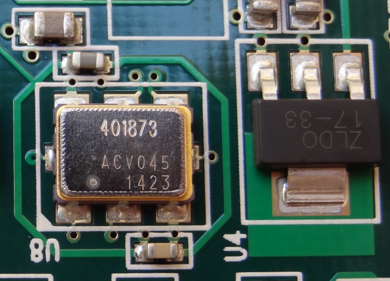
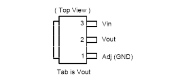
Here is the 3.3V regulator. You may add a capacitor between Vout and GND (pins 1 adn 2)


At this time I would be doing a standard installation before thinking of any other mod.

 
I decided to hold off on ordering the board until the new coding eliminates the between track clicks.
 
Mar 13, 2015 at 12:16 PM Post #34 of 251
Reading trough the DOY thread this morning - came on this from Soekris back in July of last year:
 
Later on I might look into doing a version with discrete non NFB output drivers, already have it in my CAD systems.... 

 
That would be interesting.
 
PS Here is the thread for anyone interested.  I've been scanning for PS options beyond the 7-8V torodial
http://www.diyaudio.com/forums/vendors-bazaar/259488-reference-dac-module-discrete-r-2r-sign-magnitude-24-bit-384-khz-5.html
 
Mar 13, 2015 at 5:56 PM Post #35 of 251
Ok, having lived for more than a month with the thing in my system, I think I have more than enough info to put together something review-like.
 
It's a really a good dac for the price asked. With the general lack of diy dacs it's a nice gust of fresh air. The biggest problem of the dac is the tremendous oversell its inventor did early on. It's a unique design that lacks many of the usual delta sigma characteristics without suffering from lack of resolution. Is it the be-all-end-all design, everyone is waiting for? Most likely not.
 
For one it is painfully evident that Soren first listened to the DAC only when he started shipping. The board and firmware has a few glaring shortcomings that could have been rectified with a rev.0 build and some beta testing. Stock 44.1kHz filters are passable at best and don't do justice for the dac, filter swap is a must. The PSU section is adequate, however it shows that the designer is not too acquainted with bipolar PSU design. It won't affect the sound, mind you, but it can kill your speakers if you keep the amp on whilst powering the DAC down. Same goes for dac behavior in Fs change - it loses lock and skips about 3 seconds of material. This is unacceptable. Soren promises a revised firmware to correct this - will report on results.
 
I'd say - wait for a rev.2 board. Too many bugs for neophytes to deal with.
 
Mar 13, 2015 at 6:12 PM Post #36 of 251
  Ok, having lived for more than a month with the thing in my system, I think I have more than enough info to put together something review-like.
 
It's a really a good dac for the price asked. With the general lack of diy dacs it's a nice gust of fresh air. The biggest problem of the dac is the tremendous oversell its inventor did early on. It's a unique design that lacks many of the usual delta sigma characteristics without suffering from lack of resolution. Is it the be-all-end-all design, everyone is waiting for? Most likely not.
 
For one it is painfully evident that Soren first listened to the DAC only when he started shipping. The board and firmware has a few glaring shortcomings that could have been rectified with a rev.0 build and some beta testing. Stock 44.1kHz filters are passable at best and don't do justice for the dac, filter swap is a must. The PSU section is adequate, however it shows that the designer is not too acquainted with bipolar PSU design. It won't affect the sound, mind you, but it can kill your speakers if you keep the amp on whilst powering the DAC down. Same goes for dac behavior in Fs change - it loses lock and skips about 3 seconds of material. This is unacceptable. Soren promises a revised firmware to correct this - will report on results.
 
I'd say - wait for a rev.2 board. Too many bugs for neophytes to deal with.

 
Thanks for this great update and summary RW!  My recollection is that misterrogers reported at one point (on another board) that he wasn't experiencing the skipping issue, but was using something other than an amanero for usb?  Is that considered a viable end run around the firmware issue?
 
I have yet to try my hand at a diy dac, and the relative simplicity of this compared to all the modules required for a TPA kit makes it pretty appealing.  Sounds like waiting on rev.2 is really the prudent move though.  
 
Mar 13, 2015 at 7:04 PM Post #37 of 251
  Ok, having lived for more than a month with the thing in my system, I think I have more than enough info to put together something review-like.
 
It's a really a good dac for the price asked. With the general lack of diy dacs it's a nice gust of fresh air. The biggest problem of the dac is the tremendous oversell its inventor did early on. It's a unique design that lacks many of the usual delta sigma characteristics without suffering from lack of resolution. Is it the be-all-end-all design, everyone is waiting for? Most likely not.
 
For one it is painfully evident that Soren first listened to the DAC only when he started shipping. The board and firmware has a few glaring shortcomings that could have been rectified with a rev.0 build and some beta testing. Stock 44.1kHz filters are passable at best and don't do justice for the dac, filter swap is a must. The PSU section is adequate, however it shows that the designer is not too acquainted with bipolar PSU design. It won't affect the sound, mind you, but it can kill your speakers if you keep the amp on whilst powering the DAC down. Same goes for dac behavior in Fs change - it loses lock and skips about 3 seconds of material. This is unacceptable. Soren promises a revised firmware to correct this - will report on results.
 
I'd say - wait for a rev.2 board. Too many bugs for neophytes to deal with.


+1 Thanks for the review.  Reading about these beta like issue has held me back from moving forward with the project.  The next rev will likely have improvements to the PSU.
 
Mar 19, 2015 at 10:02 AM Post #39 of 251
 
+1 Thanks for the review.  Reading about these beta like issue has held me back from moving forward with the project.  The next rev will likely have improvements to the PSU.

 
I’ve not seen Søren at any point imply his power design isn’t adequately. Rather the opposite. What have been proven is that the 3.3V output isn’t a good way to power your optical receiver. That might not be considered a problem as they’re main purpose is to let us have easy access to reference voltages.
 
My understanding is that all R&D from now on is firmware related only. Søren have from the start been up front about us getting beta sw to play with. I only wish he would release it frequently rather than sitting on it as he now does. The thump issue alone is important enough for us to get an update in my book. And he have in some way already solved it as I read it. But my understanding is that his current implementation has an 300ms cut at the start of track when fs change. Rather have that than defect speakers or amp.
 
Mar 19, 2015 at 10:24 AM Post #40 of 251
   
I’ve not seen Søren at any point imply his power design isn’t adequately. Rather the opposite. What have been proven is that the 3.3V output isn’t a good way to power your optical receiver. That might not be considered a problem as they’re main purpose is to let us have easy access to reference voltages.
 
My understanding is that all R&D from now on is firmware related only. Søren have from the start been up front about us getting beta sw to play with. I only wish he would release it frequently rather than sitting on it as he now does. The thump issue alone is important enough for us to get an update in my book. And he have in some way already solved it as I read it. But my understanding is that his current implementation has an 300ms cut at the start of track when fs change. Rather have that than defect speakers or amp.


+1 Thanks for your comments and updates.  I haven't read the whole DIY thread yet.  As soon as the thump issue is solved I will order a board. It would be nice to have updated filters as well.  I'd rather get it pre-loaded, then have to go the update route.
 
I was only relating to what he had posted on the DIYAudio thread I quoted back in post #34 - maybe wishful thinking on both our parts.
 
Side note - anyone have a link to a nice, inexpensive case for this board with lot's of room inside?
 
If he can get a few of these bugs worked out - he has a very viable product.  I could see overseas audio manufacturers ordering a large quanity of these to build lower cost DACs around.  Like what we are seeing with the XMOS chipset and USB converters.
 
PS - You are right - I should have said output drivers not PS, relating to possible board design changes.  As I hope to use a tube driver or tube buffer output this is not a big deal.
 
Mar 19, 2015 at 10:47 AM Post #41 of 251
Here are some good mods for the PS on the board:
 
https://hifiduino.wordpress.com/2015/02/22/dam1021-r-2r-dac-mods/
 
  ADDING CAPACITORS
While examining the back of the board and realizing that J2 cannot be used as input power, I figure it is the perfect place to add capacitors to the power lines. Decided to add 330 uF Oscons to the digital 1.2V and 3.3V and Panasonic FMs to the +/- analog lines. This mod is completely reversible. Just cut the leads. I first soldered a row of pins and the capacitors are soldered to the pins.
Adding capacitors to the analog lines further improves the filtering because it is an RC filter.
There is still the +/- 5V lines but there is no more space. I chose not to add capacitors these lines because the 5V regulators already have large output capacitors, and because I thought they would benefit the least: if you examine the backside of the board, you’ll notice that the connectors at J2 trace from different places in the board. The longest traces are from the +/- 5V regulators.

These power mods are “approved”: [link]
If you insist to improve the on-board power supply, try replacing the 6 electrolytic capacitors with aluminum polymer types, 1000u 16V exist in same 10mm SMD footprint and t.ex. digikey stock them at $2.20 each. Should be easy to replace.
You can also add a small polymer electrolytic on the 3.3V output, but please note that the clock oscillator power already have a filter, so I doubt it will make any difference.
Didn’t want to remove the existing capacitors and risk damaging something. It is too early to do any kind of surgery on the board :). Plus the existing filter capacitors don’t seem quite easy to remove given that there is very little space between them.

 
Apr 10, 2015 at 3:25 PM Post #43 of 251
  Don't leave me alone. And subscribed.
 

I'm waiting for a few of the initial release bugs to get fixed in a firmware update and possible 1.1V board release.  I'll then order one to proceed with the build, initially using the on board SS output stage then later using a separate tube board - if I can find a compatible one (Tao-Bao?).  PS likely be a straight cheap Toroidal to get it working, then moving a better Rcore or EI transformer.  I'm learning a lot from the Gustard thread on the pluses and minuses of the available options.
 
Cheers!
 
Apr 10, 2015 at 4:11 PM Post #44 of 251
  I'm waiting for a few of the initial release bugs to get fixed in a firmware update and possible 1.1V board release.  I'll then order one to proceed with the build, initially using the on board SS output stage then later using a separate tube board - if I can find a compatible one (Tao-Bao?).  PS likely be a straight cheap Toroidal to get it working, then moving a better Rcore or EI transformer.  I'm learning a lot from the Gustard thread on the pluses and minuses of the available options.
 
Cheers!

 
Hello Rb2013,
 
I might assist you in TaoBao, but please let me know in more details of the item(s) that you are looking for.  
 
I look forward for your reply.
 
 
Regards,
 
Apr 10, 2015 at 4:55 PM Post #45 of 251
   
Hello Rb2013,
 
I might assist you in TaoBao, but please let me know in more details of the item(s) that you are looking for.  
 
I look forward for your reply.
 
 
Regards,

Thank you for your kind offer.  I would be looking for a tube output board using the 6922.  That would only require a PS and input and output hookups.  I have found these but they use a different tube.  I wanted something like the tube output stage of the Lite DAC60.
 
This one is close - but I would like the 6922 tube vs the 6n3p-ev
http://www.ebay.com/itm/Tube-output-stage-for-cd-player-or-dac-upgrade-/190613962046?pt=LH_DefaultDomain_0&hash=item2c617a3d3e
 
This one looks like overkill:
http://www.ebay.com/itm/LITE-LS60-Assembled-Balanced-Tube-Preamplifier-Board-12AU7-6DJ8-6922-/181712540779?pt=LH_DefaultDomain_0&hash=item2a4ee9546b
 

Users who are viewing this thread

Back
Top