The "Lovely Cube" Headphone Amp (Lehmann Black Cube Linear Clone)
Sep 26, 2012 at 1:36 AM Post #991 of 1,624
Quote:
Any thoughts on this question?


15-0-15v 1A 
 
I've also used a 18-0-18V 1A with no ill effects other than a little more heat.
 
Toriods are usually better than most wall warts. They do sell toroid-in-a-box that look like wall warts, else hunt around ebay for "medical grade" power supplies.
 
Sep 26, 2012 at 3:29 AM Post #993 of 1,624
thanks guys!
 
Board and power supply are on order - "wall wart" for now - I may build a better power supply later. 
 
Oct 7, 2012 at 6:05 PM Post #996 of 1,624
Quote:
The best upgrade in their place is a piece of wire.


Excellent. And 10 mV DC offset becomes 40-80 mV offset on output.

I doubt that all people walk with multimeter in pocket and can always check if DAC has DC offset or not.
 
Stay with input capacitors. MCap are excellent. Old ERO (big blue box) are very good. Losses are close to none.
 
 
Oct 8, 2012 at 6:34 PM Post #997 of 1,624
Do you know any linear sources providing offset on their output? Most of them is AC coupled. BTW, offset produced by the output stage is of comparable level and there is no feedback loop in this amp to compensate it. I bypassed those big blue ERO and it showed that they weren't that excellent. When insisting on AC coupling, add a quality bipolar cap parallel to the film cap.
 
Oct 9, 2012 at 2:34 AM Post #998 of 1,624
Quote:
Do you know any linear sources providing offset on their output? Most of them is AC coupled. BTW, offset produced by the output stage is of comparable level and there is no feedback loop in this amp to compensate it. I bypassed those big blue ERO and it showed that they weren't that excellent. When insisting on AC coupling, add a quality bipolar cap parallel to the film cap.

 
Any output source has DC offset, unless it has capacitor in series that block DC component.
Feedback loop is not here because that involves more components and problems with ringing and oscillating if feedback loop is not made in proper way. Furthermore, if there was feedback loop, OPAMP rolling would be dangerous because LM xx, BB xx and AD xx are different speed and behave in different way so, simple said, every OPAMP needs specially tuned feedback loop for best performance.
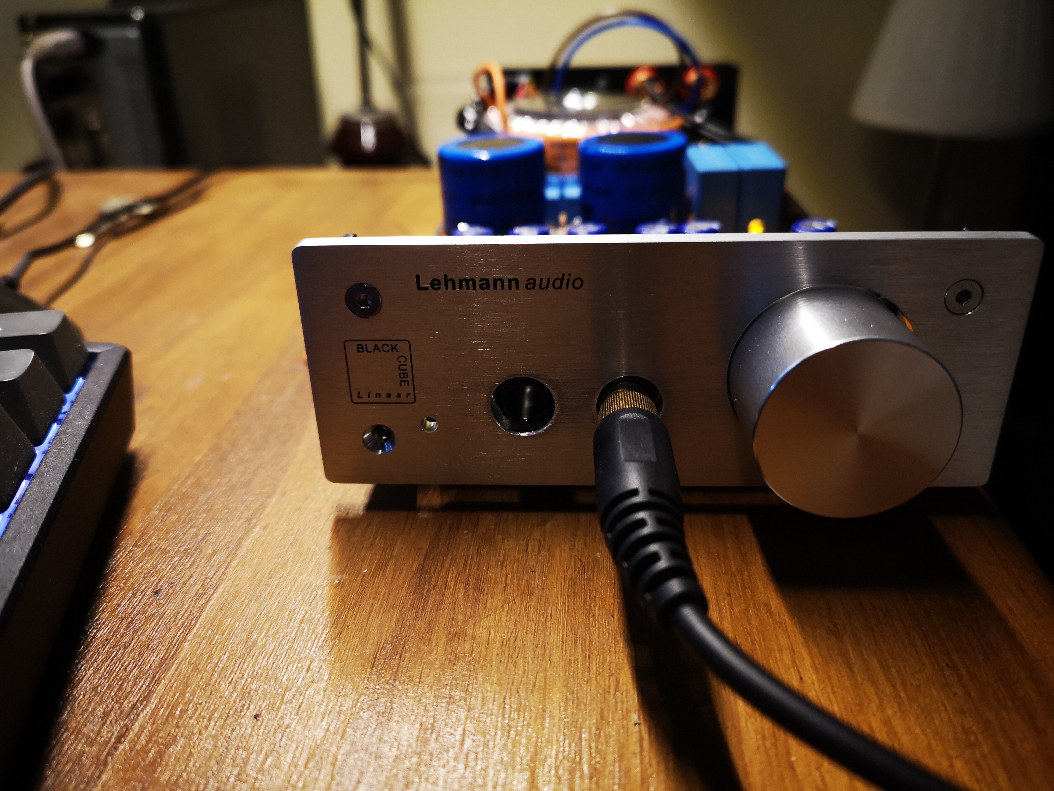
Output source that is made directly from OPAMP output (without buffer) involves default DC offset that is stated in tech specs plus DC offset on input (multiplied by gain). Naked out from OPAMP might be excellent choice but has two bad things. First is that you can not down DC offset with output capacitor because OPAMP does not like capacitive load (usually) and when it does, it needs additional compensation and feedback loop (more components). Second is that output resistance falls to low level (usually 50K ohm) and we all know that OPAMP in tech charts specifies minimum load when it gives specified performance (some need 1kOhm some 10 kOhm, etc..). But generally, the bigger load the better performance. In Lovely Cube (Black Cube Linear, Matrix M stage) output resistance (what buffer sees) is 10 Ohm which is high and can be lower to 2.2 Ohm with changes in resistance (1.5 kOhm resistor to 2.5 kOhm) but it will make amplifier prone to oscillation and OPAMP rolling will not be so easy. Current through BC 550/560 transistors will be lower and ratio between BC/BD transistor current will be higher - reason for oscillation - needs better noise control and source and tightly matched transistors.
The most important thing is what kind of load sees OPAMP now (with bufFer). it sees almost pure resistive load (buffer) and its (buffer) resistance is close to 160 kOhm. 160 kOhm is enough for every OPAMP to behave within specs. Only reason what people see difference between diamond buffer and naked OPAMP out - is in load resistance. A pure technical reason without voodoo magic.
After I researched few things and make few Lovely Cube amplifiers I fount out something what makes me laugh. And that is - biasing OPAMP in A class. If we want to bias something in A class we need DC current through buffer, OPAMP or output stage or middle stage. Whatever... Our case - BJT transistor, that will always be in ON state and in area where BJT transistor behaves like amplifier (most important thing!). If we want to bias OPAMP in A class it is almost like we drive voltage amplifier (preamp) in A class. If OPAMP must drive 160 kOhm load then how much it needs to be driven in A class? Well, it needs only 40-80 uA. Improvement that people see when they connect 5 kOhm resistor between OPAMP out and negative rail is just opposite (downgrade) because it involves two things: noise from supply source directly to OPAMP out, and low resistance (OPAMP now must handle higher current where 98% represents pure heating and buffer becomes useless).
 
When high resistance buffer is in output stage (represents current source), biasing OPAMP in A class with DC current more than 200 uA is total nonsense.
 
Oct 9, 2012 at 3:35 AM Post #999 of 1,624
Most sources have capacitors in series and that's why you don't need another. If you care so much for the offset matching then remove 10k resistor in series with these capacitors before the op-amp input and place there something matched (depending on the op-amp) and remove the 100pF capacitors to ground. I've got the MSc degree in Electronics Engineering and I don't need explanation what is the difference between open loop and close loop buffers. I I've been modding this kind of amps since more than three years, different flavors of the BCL circuit. Biasing modern op-amps into class A is obviously stupid and there is more bad things about it than good, including distortions. The easiest protection from capacitive loads are series resistors. No more than 75 ohms will work but it's not necessary here as much as capacitors in series anywhere else.

I mentioned the open loop discrete buffer because it's never compensated thermally enough to justify strong fight for stringent offset numbers anywhere else in the circuit. 40mV is pretty normal and either you match the transistors and resistors in the buffer (good for people having much time to spend on it) or you accept it and don't care for another couple of mV appearing somewhere else.

BTW, the output impedance of the diamond buffer is 5 ohms, not 10 (as you read from the resistors) and I would leave it as it is.
 
Oct 9, 2012 at 7:27 AM Post #1,000 of 1,624
I would not remove 10k resistors because ALPS pot has always the same resistance but not on OPAMP side. It has always 50k on source side. On OPAMP side there is variation between 50 kOhm and 0 kOhm. So if I remove 10k resistor, when volume is close to maximum, I will get 50k resistance to ground (through volume pot). When pot is close to zero I will get 0 ohm to ground at input.
100 pF capacitor acts as filter that blocks frequency (- 3dB) over 25 kHz (when pot is close to zero) and 160 kHz when volume is at maximum. So here, lots of things are hovering around and in this case it is hard to optimize input signal for opamp because it depends on volume pot that changes entire characteristic (frequency with 100pF capacitor, and resistance). If I remove capacitor then I have to place 100 kOhm resistor on its place but with that I get nothing special because of potentiometer (50 k). I changed 100 pF capacitor with 51 pF and that changed magnitude and phase little bit. Which is good because attenuation is less but not so good because opamp might start to oscillate. Frequency range of input filter now goes from 52 kHz to 310 kHz.

It really does not matter if it is 5 or 10 ohm because Grado needs 4 ohm to be properly damped, and Denon needs 2-3 Ohm. The lower the better. There is no problem if that resistance falls below 2 ohm. Problem is in heating because design of heatsinks can not handle so much heat. Heat goes up if I leave 1.5k resistors in BD circuit in the same time as output resistance falls to 2 ohm. That lifts DC current from 35 mA to 150 mA. And that current represents A class biasing.
Btw. stock LC buffer works in AB class (35 mA) when volume pot goes over 1/2 and amplifier drives low impedance headphones (Grado, Denon).
 
I am not so educated. I work as gigolo in local club. Between two chicks I mess with electronics. Girls like that.
 
Oct 9, 2012 at 2:01 PM Post #1,001 of 1,624
My Grado sound best a bit above 5 ohms and 6 ohms is maximum. More makes them too bassy, however I'm talking about a completely different amp. Regarding the ceramic lowpass capacitors, as you mentioned, their filtering point is floating with volume anyway and the resistors allow to narrow the bandwidth swing but actually you can remove them and most op-amps will remain stable.
 
Nov 9, 2012 at 2:16 PM Post #1,003 of 1,624
Maybe someone can help me. I've bought a kit, soldered it, then turn it on and... it works. But. A DC offset on output was about 200mV on a first channel, and 5V on the second channel. I've checked opamps Vcc and it also wasn't correct. So i've resoldered a "power" section of the BCL and there is still a problem. Resistors after a rectifier bridge (two 4,7 ohm parrallely conected, to sets, one for + and for -) burn after i turn the power on. Also the diode which signals "power on" does not work. Does someone have any idea what is wrong?
 
Nov 9, 2012 at 2:24 PM Post #1,004 of 1,624
Could be a diode in the wrong direction?
 

Users who are viewing this thread

Back
Top