


proid
100+ Head-Fier
- Joined
- Mar 21, 2011
- Posts
- 445
- Likes
- 17
Quote:
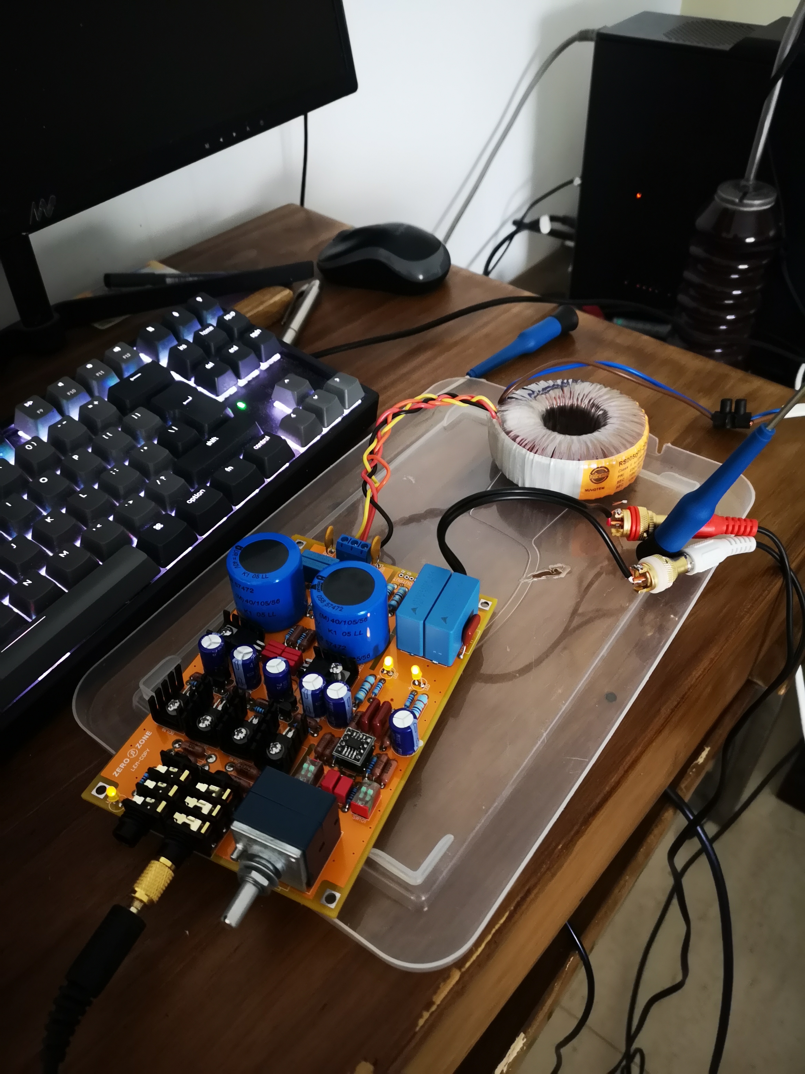
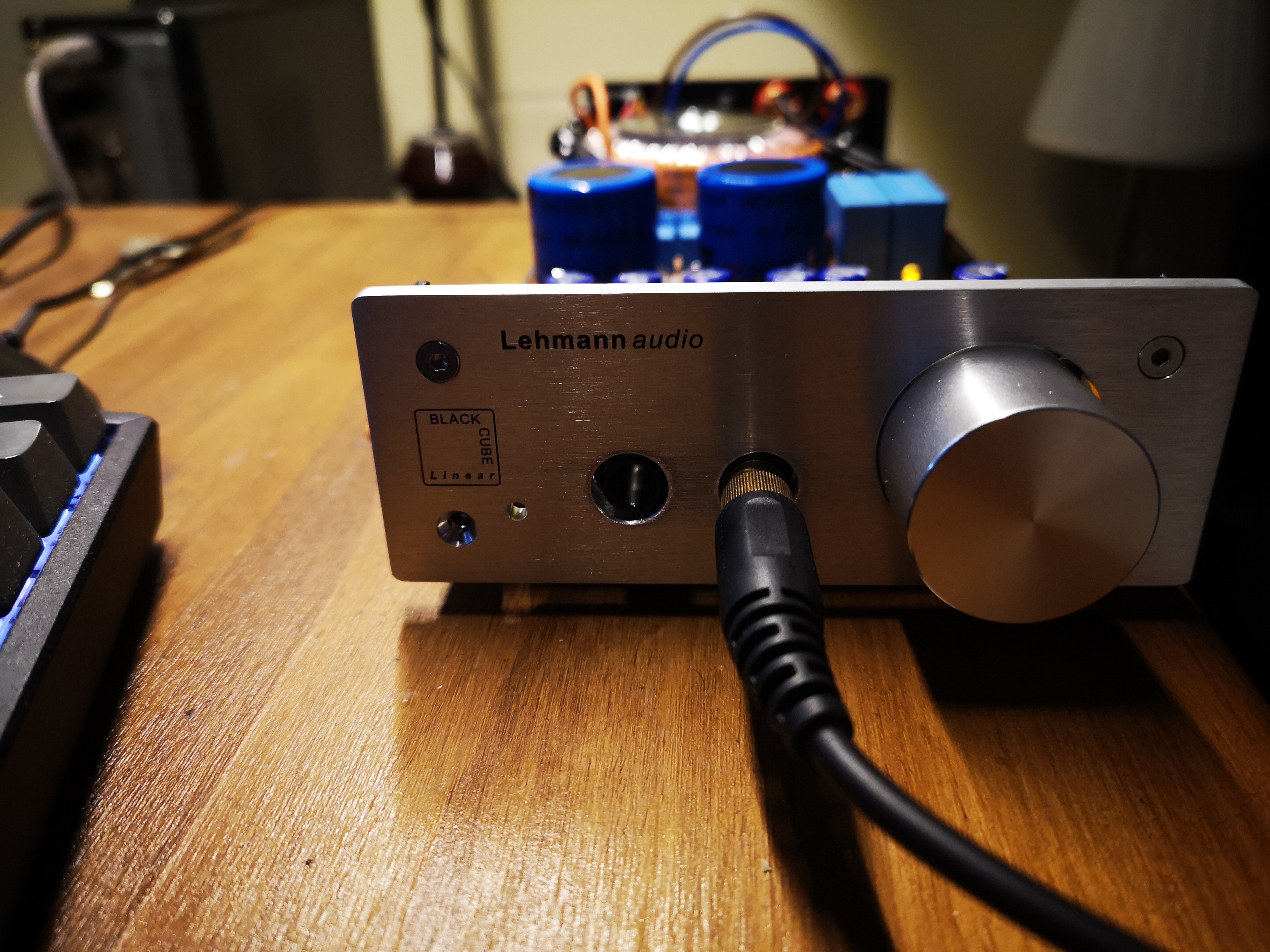
I have owned a Lehmann Audio BCL for over a year. This may not be the correct place to post regarding this amp but the upgrade mod that I have performed will apply equally to the Lovely Cube clone. I use Sennheiser HD-650s but have also used HD-800s and it is already well known that the Sennheisers match up extremely well with the BCL as they do with the Musical Fidelity X-CAN v3. In both cases, the synergy between the amp and phones is remarkable.
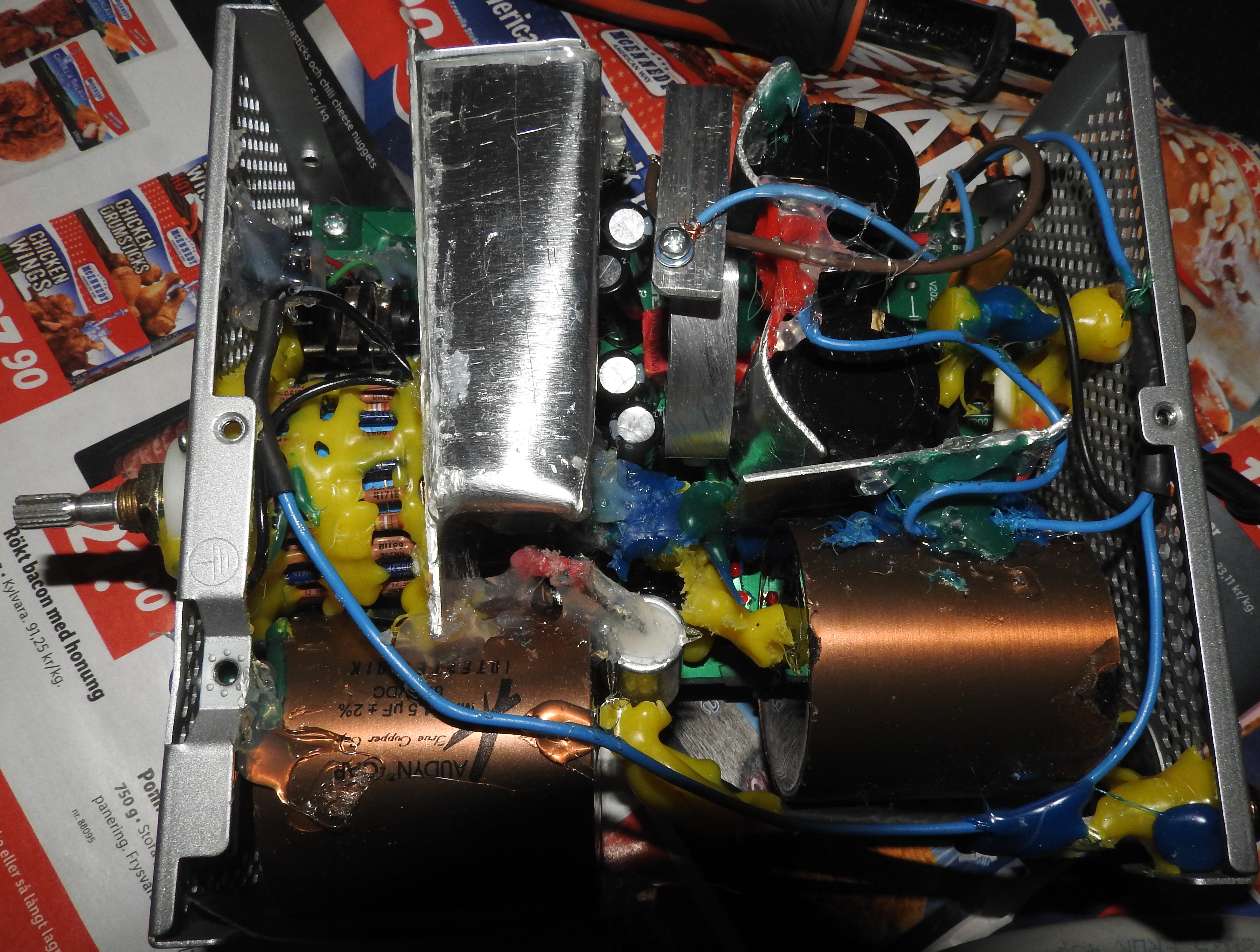
First, get rid of the input capacitors as they are polyester type (notoriously bad for good sound) and replace them with polypropylene. They are expensive but well worth changing. The larger ones are 1.5uF in the LC but 2.2uF in the BCL. Next, I would replace the Op-Amp as the OPA2134 is good but the sound is lacking in the very lowest bass registers. After trying many different Op-Amps, my personal favorite is the OPA2604 and it does not matter whether it is the original BB or the TI/BB version. If you have any acoustic music with low bass in it you will notice right away that the very lowest bass is produced well with the OPA2604 but somewhat absent with the original OPA2134. It is my absolute favorite chip and prefer it over all others including a set of OPA627Bs I have on hand. I enjoy everything about it and the amp has more detail, is plenty fast, and much better on the low frequencies while the highs remain clear and unstressed. If you do not want to solder (best way) in your choice of Op-Amp then use a really high quality dip socket. I use the Swiss made Augat brand as they are high retention type with 4-fingered contacts for reliability. It is probably the next best thing to soldering it in place.
Next, I would replace the six 470uF/35V electrolytics with Panasonic FC series and I took it one step further and replaced the Op-Amp decoupling caps with .1uF polyesters (they were .022uF originally). The main power supply capacitors were changed to Nichicon KG series Gold Tune Type II. The value was left at 4700uF each as that is more than sufficient capacity given the power level of the amp. From this point on, returns on investment with further parts changing produces diminishing returns. But I did replace resistors R13, R14, R21~R24 with PRP PR9372 metal film. The resistors used in local feedback for the Op-Amp (R21& R22) can be important and they can have a direct effect on the overall sound. Vishay Dale are very good with a neutral sound but I wanted the PRPs as they are non-magnetic and designed for audio purposes. I hope this has helped!

Can you tell me how does each mod improve the sound?
