The "Lovely Cube" Headphone Amp (Lehmann Black Cube Linear Clone)
Apr 19, 2016 at 8:47 AM Post #1,382 of 1,624
I've just got my LC up and running (prepopulated pcb). It sounds great, and especially with my dddac and srh940. Anyway, I'm thinking of how I can modify this amp and I have a few questions. I appologize if these have been answered before. 1) I have several black gate N caps. What voltages are required for the opamp decoupling caps? I have 470uf 16v and 100uF 50v. 2) does anyone have a circut diagram? 3) i was thinking of obbligato caps (have 4.7, 6,8 and10uf)as input caps (to replace the stock mkt's). Any comments?
 
Apr 19, 2016 at 9:07 PM Post #1,384 of 1,624
I've just got my LC up and running (prepopulated pcb). It sounds great, and especially with my dddac and srh940. Anyway, I'm thinking of how I can modify this amp and I have a few questions. I appologize if these have been answered before. 1) I have several black gate N caps. What voltages are required for the opamp decoupling caps? I have 470uf 16v and 100uF 50v. 2) does anyone have a circut diagram? 3) i was thinking of obbligato caps (have 4.7, 6,8 and10uf)as input caps (to replace the stock mkt's). Any comments?

 
The diagram and BOM are listed on page 2 of this thread in this post: http://www.head-fi.org/t/501046/the-lovely-cube-headphone-amp-lehmann-black-cube-linear-clone/15#post_6784844
 
Apr 21, 2016 at 8:36 AM Post #1,385 of 1,624
Hi, thanks. However I still need help to find what the minimum voltage the decoupling caps for the opamps need to be. Can I use black gate 100uf 16v in this position? Also is 4.7uF on output ok, or should I stick with a lower value as per the bom. I should point out that I have no output cap on my dac... Thanks for any answers.
 
Apr 30, 2016 at 7:43 AM Post #1,387 of 1,624
Hi, I use my cube mainly as a preamp using the cd5005 for phones.
Is there a way to permanantly disable the headphone out circuitry as I need to wind the volume right up for my AKG phones and I am concerned that I will forget and switch the amp on at almost full volume.
 
Would the lack of the phones facility improve the sound of the cube.
 
May 14, 2016 at 10:05 PM Post #1,388 of 1,624
I've been playing around with the components and finally settled on the final configuration.  I got a new board off of that large on-line marketplace and got the parts from Mouser and Digi-Key.  


For the opamp, I did a blind test, putting a piece of electrical tape over the top of the chips I had on hand (OPA2134PA, OPA2227PA, OPA 2107AP, AD823AN, JRC2068D, and NE5532P).  Signal chain was as follows:  Foobar2000 on a Windows 10 machine -> USB to S.M.S.L M8 -> Zero Zone amp -> Beyerdynamics DT990 600 ohm, AKG K7XX, and AT ATH-M50X.  Music was as follows:  Donald Fagan The Nightfly (SACD-DSF), Dire Straits Making Movies (SACD-DSF), Pink Floyd WYWH (SACD-DSF), Porcupine Tree Fear of a Blank Planet (24 Bit 48 KHz), Daft Punk Random Access Memories (24 Bit 88 KHz), and Infected Mushroom Converting Vegetarians II (Redbook FLAC).  In all honesty, with the blind test, I could not reliably tell a difference between the chips, so I stuck in the one with the least DC offset which was the AD823AN with 4.7 mV on the left and -1.5 mV on the right (with the range going from 4.7 mV to 5.4 mV for the left channel, and -3.3 mV to -1.5 MV for the right channel.
 
May 22, 2016 at 10:50 AM Post #1,389 of 1,624
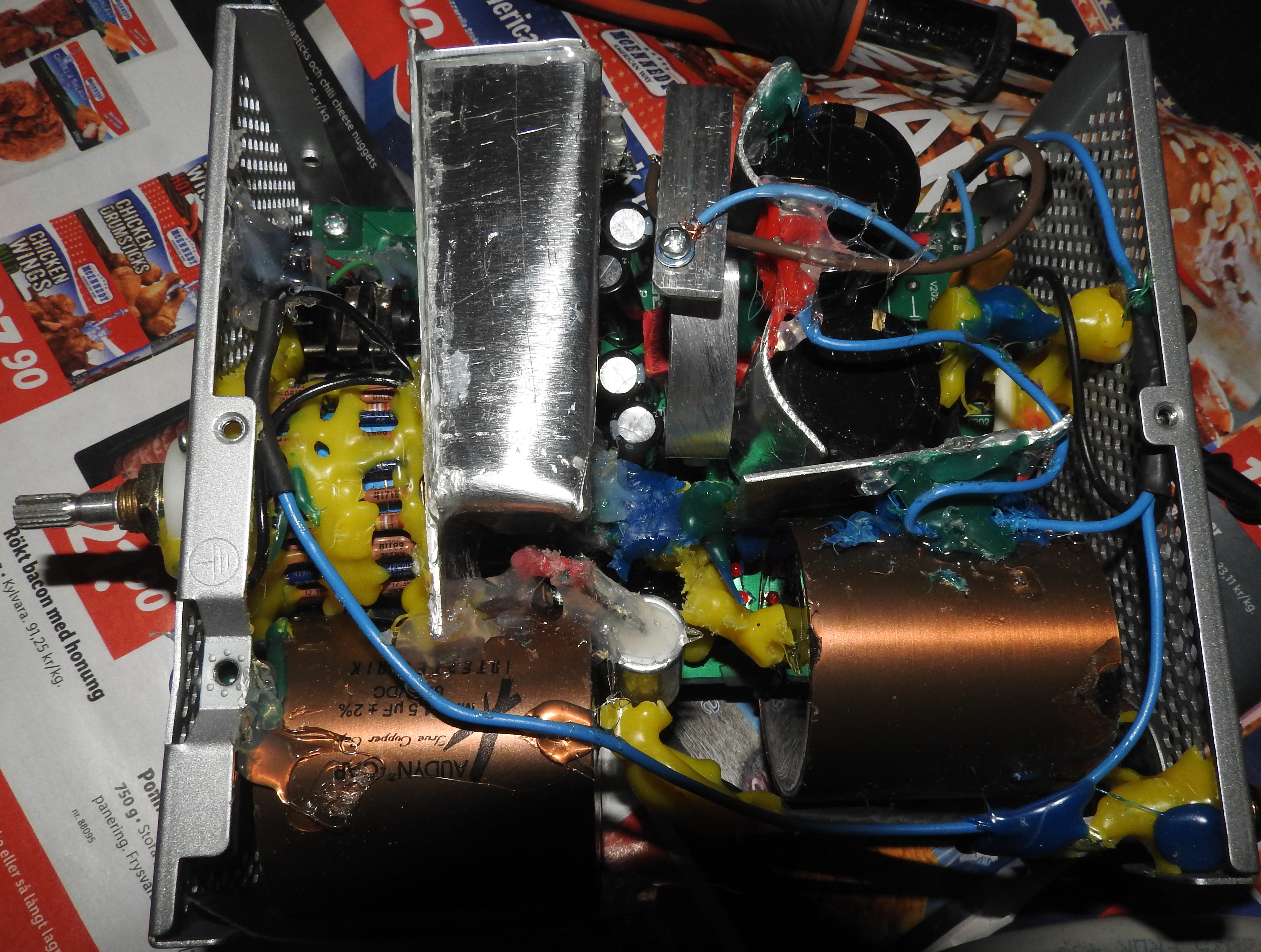
A couple of weeks ago, I finalized my portable LC amp by replacing the 4 pcs power supply caps from 100uF Muze KZ to Panasonic FR 1000uF 25V and 2 pcs Elna from 470uF to 220uF (measured paired 228uF).
 
So, here is a summary of my portable rig (carried in a backpack, driven by 14 pcs AA 2000mAh NiMH batteries):
 
The amp are connected to the source, a FiiO X5 with 2 x 64Gb Micro SDXC with FLAC´s, with a gold plated 3,5mm/2 x RCA OFC cable and RCA´s are preparred with Cardas contact conditioner. From those, the Mundorf MCap EVO bypassed with FT-1 teflon caps are soldered directly between the incoming RCA´s and the DALE 24 step ladder volume pot with shielded OFC wires (not soldered to the board).
 
To make a virtueal ground for the batteries, I use a THE2426 rail splitter/ground generator. Also, I did the Zener mod and excluded the 4 power supply resistors, the 2 PPTS fuse and also the 4 rectifier diods.
 
Finally, the the female phono jack are also soldered with some OFC cable to minimize resistance and connected to my AKG K702 single sided UP-OCC cable modded phones.
 
Other parts used in the amp: dual THS4031 mono OpAmp with 0,1uF caps, Mundorf MLytic 10000uF, BYV27-200 with MKP10 0,1uF, polystyrene caps and all resistors are Holco HP4 or DALE (except for LED´s), all assembled in a DIY aluminum enclosure.
 
And when listening with the X5 to low output, the 50K volume pot are only about 12´clock, I have to say the sound are magnificant - so detailed and sweet with an adorable sound stage. Really enjoying! 
k701smile.gif

 
May 29, 2016 at 11:37 AM Post #1,390 of 1,624
Just to be 100% shure before connecting a toroidal transformer 50VAC 15 - 0 - 15 to the LC, please confirm below is the correct way to do it if it´s connectoed to 230VAC wall outlet (europe), thank´s. And should the purple wire be connected to chassi earth?


May 29, 2016 at 7:47 PM Post #1,391 of 1,624
The output side is correct.  The split coils on the input side should be connected in series if you are on 230V.  One of the red and one of the black wire should be connected together, but not to ground earth like you had drawn.


The purple wire is the screen lead.  I hooked mine (yellow and green) up to the ground on the board (grounded to chassis), which is hooked to ground earth (yellow).


May 29, 2016 at 7:48 PM Post #1,392 of 1,624
  Just to be 100% shure before connecting a toroidal transformer 50VAC 15 - 0 - 15 to the LC, please confirm below is the correct way to do it if it´s connectoed to 230VAC wall outlet (europe), thank´s. And should the purple wire be connected to chassi earth?


Do not connect it like that, it will go BOOOOM!!!
Are you on 115v or 230v mains?
For 115v mains, connect the two RED wires together and the two BLACK wires together, connect the two formed pairs on the SIDE PINS of the IEC mains connector, center PIN is Ground.
For 230v mains, connect one RED and one BLACK together, insulate them and leave them there, now, connect the two remaining cables one RED and one BLACK on the side PINS of the IEC connector.
The PURPLE wire is the electrostatic shield, connect it to Chassis GROUND.
 
May 30, 2016 at 6:36 AM Post #1,393 of 1,624
   
Do not connect it like that, it will go BOOOOM!!!
Are you on 115v or 230v mains?
For 115v mains, connect the two RED wires together and the two BLACK wires together, connect the two formed pairs on the SIDE PINS of the IEC mains connector, center PIN is Ground.
For 230v mains, connect one RED and one BLACK together, insulate them and leave them there, now, connect the two remaining cables one RED and one BLACK on the side PINS of the IEC connector.
The PURPLE wire is the electrostatic shield, connect it to Chassis GROUND.


Ok, thank´s!
 
So it is gonna be like this:
 
Please forget what I wrote earlier today, below is the correct wiring instruction:
 
Connect one RED wire to L at the IEC and one BLACK wire to N at the IEC.
 
Connect the leftover RED and BLACK with each other, but do NOT connect those to the IEC ground.
 
Connect BLUE wire to one of a hole at the side at the board and GREEN wire to a hole other side.
 
Connect the leftover BLUE and GREEN to the middle holes.
 
May 30, 2016 at 8:21 AM Post #1,394 of 1,624
 
Ok, thank´s!
 
So it is gonna be like this:
 
Please forget what I wrote earlier today, below is the correct wiring instruction:
 
Connect one RED wire to L at the IEC and one BLACK wire to N at the IEC.
 
Connect the leftover RED and BLACK with each other, but do NOT connect those to the IEC ground.
 
Connect BLUE wire to one of a hole at the side at the board and GREEN wire to a hole other side.
 
Connect the leftover BLUE and GREEN to the middle holes.

 
Right, that's correct for 230v mains.
 
Jun 10, 2016 at 6:49 PM Post #1,395 of 1,624
Can't believe this thread is still going after all these years. I'll be adding Cidious's thread on diyaudio.com to the first page:
 
http://www.diyaudio.com/forums/headphone-systems/285380-headamp-upgrading-lehmann-bcl-clone.html
 
and this thread about resolving hum on a defective board:
 
http://www.diyaudio.com/forums/headphone-systems/271057-100hz-hum-lehmann-linear-clone.html
 

Users who are viewing this thread

Back
Top