It's in the datasheet for the 5G. I don't exactly remember what VMID is, and this computer isn't loading the datasheet so that I can tell you. Yeah, it's in the datasheet.
also would it matter if I bridged the top and bottom pads together?
I'm thinking if it DID matter, maybe that's why my 4th gen is being discharged (i didn't bridge the top/bottom pads together, but I did solder 1 wire to the top pad and the other wire to the bottom pad)...hmmm
Uhm... the bottom pads are connected to the output of the DAC, the top go to the output stage. You do not want to short anything and you want to use the bottom contacts.
I emailed Wolfson once for the datasheet of the WM8350, but they said I'd have to sign a non-disclosure agreement, which totally goes against the whole point. If I had one in front of me, maybe I could figure it out. I don't intend on getting one solely for the purpose of opening it up though. Maybe if I got a good deal. We'll see.
barqy:
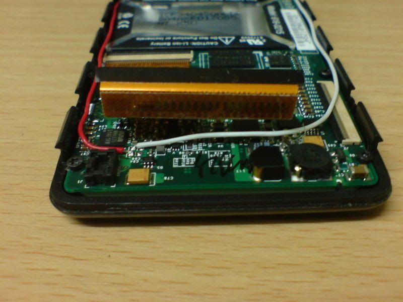
If you're talking about the 4th gen, you want to grab the signals from the rightmost pads on the left of the DAC, assuming that you're facing the iPod right-side up. I don't know why you're shorting anything, but the easiest way to avoid these problems is by following "standard procedure" and then straying from it when you know what you're doing. I still don't know which pads you used for the 4G, as I think you got FallenAngel thinking of the 5G instead of the one you're actually asking about. Maybe you should try to make your diyMod look like this one. Get rid of that solder bridge and just make it look nice and neat like this one.
You said you soldered one wire to the top pad and one to the bottom pad. This diyMod is upside down, but you should be grabbing the signals from the top and bottom pads. The more important distinction is that you took it from the pads as demonstrated in the image above.
And above all, images are the best way we can help. If you can't get the photos to us, that's cool. You're just going to have to wait longer to get it to work.
Originally Posted by Hayduke /img/forum/go_quote.gif I don't understand. What is VMID?
So you are saying the line out on pins 3 and 4 of the dock connector are muted?
No, I'm talking about the DAC chip.
OUT3 and OUT4 are alternative outputs that can use the same mixers as the HP out but they can run at higher voltage like the line out. They can even run higher @ over 2V if the 'boost' is enabled.
Apple have muted these outputs so you can't use them in favour of allowing a DC coupled output on the HP.
Look at my earlier post ref the application note, or on the spec sheet, for more information on DC coupled HP out.
Basically it allows you to use the HP out without capacitors by raising the ground to the same voltage potential as the outputs. You connect the ground wire to the VMID pin instead of a common ground connection.
*****Not recommended if you do not understand the grounding requirements of your amp*****
Originally Posted by no_eye_dear /img/forum/go_quote.gif No, I'm talking about the DAC chip.
OUT3 and OUT4 are alternative outputs that can use the same mixers as the HP out but they can run at higher voltage like the line out. They can even run higher @ over 2V if the 'boost' is enabled.
Apple have muted these outputs so you can't use them in favour of allowing a DC coupled output on the HP.
Look at my earlier post ref the application note, or on the spec sheet, for more information on DC coupled HP out.
Basically it allows you to use the HP out without capacitors by raising the ground to the same voltage potential as the outputs. You connect the ground wire to the VMID pin instead of a common ground connection.
*****Not recommended if you do not understand the grounding requirements of your amp*****
TTFN
I looked at the data sheet after I posted that. I started to understand what you meant, but you confirmed it. Thanks. It's nice to know that I did understand the data sheet
Originally Posted by joneeboi /img/forum/go_quote.gif How flattering that you'd sign up just to post in this thread. Welcome to head-fi, sorry about your wallet.
Headphone functionality
If you do it the way specified on the front page, then you should retain the headphone jack signal.
Capacitor SQ
That ultimately comes down to the overall sound of your rig. What headphones (/amp/cables/other accessories) are you using? I love my diyMod 4G with Black Gate NX Hi-Q 47uF 6.3V to PIMETA with AD8620/AD8610 + TREAD through my rescreened Grado Labs SR60s with Canare Star Quad recable, Grado Labs Jumbo Pads with glue mod and sticky tack driver mod. I was told at a meet that my headphones sounded better than another member's GS1Ks, but again, it all completely comes down to your sound preference and rig.
Short answer goes something like "Find the sound you like on your rig. I like the BG NX Hi-Q 47uF 6.3V in my system."
Internal Capacitor
It depends on what caps you want to use and what other mods you've done to your iPod. gueri_fr proved to us that internal caps was a possible option when you did the CF mod. So far as I know, others have not been able to reproduce the internal caps, but we never say 'die' in DIY, do we?
If you somehow figure another way, do share with us.
Docking Speakers
They won't work unless there is some method of keeping the DC from getting to the speaker. It boils down to each speaker docking station, so one can't really say for sure. Generally, I would say they wouldn't have that protection because there isn't a threat of DC being in the signal with the stock iPods, but again, you can never really say for sure. Why don't you open your speaker dock and find out?
Thank you for your prompt reply. I was thinking that if you replace the 80 gig drive with a 30 gig, or if you can obtain an 80 gig backing, you might be able to squeeze the Caps into the casing, just a thought. Also if you did not get rid of the original Caps and just wired the DiyMod in parallel wih the orig. setup, and also install a switch, would you be able to say switch the switch off and still have docing capabilities, or would the DiyMod just not work if it is wired in Parallel to the orig. Caps?
You could certainly install a switch. If you want to keep the line out to pins 3 and 4, I imagine you would have to incorporate the switch into the iPod itself. Another way would be to put the switch into the cable or after the cable and wire the line out straight to an unused dock pin. You'd need at least a DPDT, or double-pole-double-throw, switch, so space may become a factor depending on which one you get. That might be nice for comparisons.
Originally Posted by joneeboi /img/forum/go_quote.gif You could certainly install a switch. If you want to keep the line out to pins 3 and 4, I imagine you would have to incorporate the switch into the iPod itself. Another way would be to put the switch into the cable or after the cable and wire the line out straight to an unused dock pin. You'd need at least a DPDT, or double-pole-double-throw, switch, so space may become a factor depending on which one you get. That might be nice for comparisons.
So if I were to wire it in parallel to the original, both would work fine right? Then I would wire the parallel lines to an unused part of the dock, and make a 30 pin connector with line out that corresponds to the part of the dock that I used earlier, right? Thanks again.
Originally Posted by mbarry /img/forum/go_quote.gif So if I were to wire it in parallel to the original, both would work fine right? Then I would wire the parallel lines to an unused part of the dock, and make a 30 pin connector with line out that corresponds to the part of the dock that I used earlier, right? Thanks again.
I think I understand what you're saying. That was my original plan too. I was going to run wires from the DAC to unused pins on the dock connector, then make 2 LOD's to compare them. I like the idea of a switch in the LOD. It would be something to build just for that one experiment though
I was actually planning (key word here; notice I didn't say "implementing") a capacitor comparison box, where a 2P6T rotary switch allowed you to try up to 6 different pairs of capacitors. In my experience, the total number of poles doesn't go higher than 12, so six pairs of capacitors is the limit. It would be a mighty fine tool to use to find the best capacitor for your rig. What good would it be unless it were low cost and transportable? Hm...Could it be used to float around the world to help diyModders find the best capacitor for their setups? Not very useful but for a few moments. In that case, it ought to be very small and easily shipped. Should I be thinking out loud like this?
I modded an ipod mini 2G : I remove the 6 caps and I soldered well the cable and I still have sound when I use it without the blackgates (I tried in a soundstation). Is it normal ?
I thought if I don't use a cable with BG caps I will hear noise and not the music : am I wrong ?
This site uses cookies to help personalise content, tailor your experience and to keep you logged in if you register.
By continuing to use this site, you are consenting to our use of cookies.