


rexirius
New Head-Fier
- Joined
- Jan 30, 2013
- Posts
- 43
- Likes
- 10
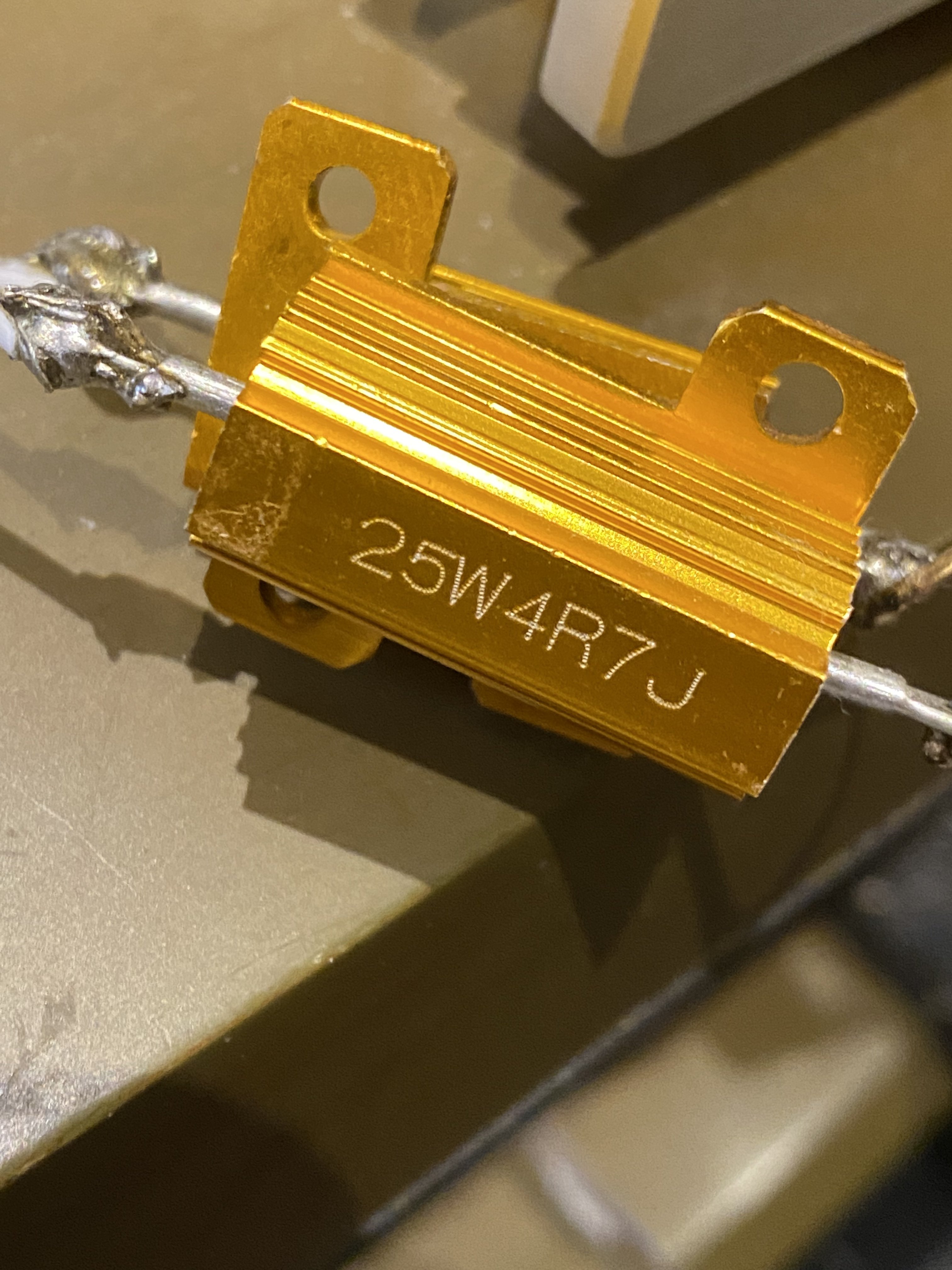
Instead of resistors, can we use the attenuators recommended in the Magni thread:
http://www.parts-express.com/pe/showdetl.cfm?partnumber=266-244
Do they serve the same purpose of presenting the amp with a load? Or do they work in a totally different way?
Thanks!
http://www.parts-express.com/pe/showdetl.cfm?partnumber=266-244
Do they serve the same purpose of presenting the amp with a load? Or do they work in a totally different way?
Thanks!


