Speaker amps for headphones
Sep 25, 2014 at 7:49 AM Post #2,746 of 3,871
What's the easiest (yet accurate) way to determine if a 75-Ohm "digital" cable is actually 75-Ohm?
 
(Armaegis graciously comes to my rescue in 3, 2, 1...)
 
biggrin.gif

 
Sep 25, 2014 at 7:53 AM Post #2,747 of 3,871
A multimeter of course.
 
Sep 25, 2014 at 8:51 AM Post #2,749 of 3,871
  Used precisely how?
 
In other words, is it OK to short the other end of the cable with a screw driver wedged into the male RCA connector or should I attach it to a female RCA jack that's been shorted with a well soldered bit of heavy gauge stranded copper wire, or am I over-thinking this, or ?
 
biggrin.gif

You could also just measure either end of the cable for starters 
biggrin.gif

 
Sep 25, 2014 at 12:59 PM Post #2,750 of 3,871
Whether the output is SE or bridged (balanced, differential), the outputs should have minimum DC offset relative to signal common.
Measure the DC offset to be sure.

 
Bolded for emphasis. But again some amps have weird noise on both terminals which is cancelled out. Yeah in theory it shouldn't have any to begin with, but schiit happens and tying two noisy negatives together can obliterate the cancellation that you need.
 
Just being a namby pamby negative Ned.
 
 
  What's the easiest (yet accurate) way to determine if a 75-Ohm "digital" cable is actually 75-Ohm?
 
(Armaegis graciously comes to my rescue in 3, 2, 1...)
 
biggrin.gif

 
Short answer... you can't.
 
For starters, measuring impedance technically isn't the same as measuring resistance, although in the case of a headphone driver the resistance is sorta-close-enough as long as you ignore the impedance peaks (and in the case of a planar, the resistance is basically the same as the impedance all the way through).
 
Even trickier, when we talk about cables we're actually talking about "characteristic impedance" which is different frmo regular impedance. This is a measured value of a yadda yadda infinitely long cable and the reflections of the signal within yadda yadda.
 
Another short answer: most digital cables aren't actually 75 ohms (characteristic). This requires that both the cable and the termination are both 75. The output and receiving end are supposed to be as well, but often aren't.
BUT... you probably would never notice anyways.
 
Sep 25, 2014 at 4:58 PM Post #2,751 of 3,871
   
Short answer... you can't.
 
For starters, measuring impedance technically isn't the same as measuring resistance, although in the case of a headphone driver the resistance is sorta-close-enough as long as you ignore the impedance peaks (and in the case of a planar, the resistance is basically the same as the impedance all the way through).
 
Even trickier, when we talk about cables we're actually talking about "characteristic impedance" which is different frmo regular impedance. This is a measured value of a yadda yadda infinitely long cable and the reflections of the signal within yadda yadda.
 
Another short answer: most digital cables aren't actually 75 ohms (characteristic). This requires that both the cable and the termination are both 75. The output and receiving end are supposed to be as well, but often aren't.
BUT... you probably would never notice anyways.

 
Dang, I figured it was more complicated than what I had in mind, but was clueless just the same.  Thanks for relieving me of trying to test it - I'll just "trust" that the manufacturer is telling the truth.
 
Sep 25, 2014 at 5:01 PM Post #2,752 of 3,871
   
You've got the right idea in the bolded part there, sorta. There's a schiitton of pseudoscience tossed about and I want to be careful not to get dragged into "sound science"... but here's a overview:
 
- a lof of the ideas of differential scattering (ie: different frequencies will diffract at different angles, thus take longer/shorter paths to the destination) are valid... but do sorta require that the impediments in question are within an order of magnitude of the wavelengths
- nevermind that this scattering thing is kinda based on the idea of a particle zipping from source to destination, which is really not how electricity works... a wire is more like a hydraulic tube with your source acting as a piston (fun thought experiment: now think of the whole voltage amps vs current amps as a pressure vs flow rate thing and imagine what kind of a change in architecture that entails)
- grain boundaries and impurities do affect overall electrical conductivity, sorta like dirt or obstructions
- does this affect "pressure" from source to destination in the audible frequency range? well that's a debate for sound science. I think I can safely assert that it does interfere with the ultrasonic garbage from DSD though
- as a whole though, a high purity low grain boundary metal is good, if nothing else strictly from the perspective of resistance to oxidation/corrosion
- except your voice coils aren't made from it
- not the circuit traces in the amp, nor the leads on any of the components


And thanks for this, too!
 
Sep 25, 2014 at 9:57 PM Post #2,753 of 3,871
Bolded for emphasis. But again some amps have weird noise on both terminals which is cancelled out. Yeah in theory it shouldn't have any to begin with, but schiit happens and tying two noisy negatives together can obliterate the cancellation that you need.

Just being a namby pamby negative Ned.


Not too sure what post you are answering.......:confused_face_2:

An amplifier with a balanced output should still have zero DC offset on both the inverting and non-inverting outputs WRT signal common.
Irregardless, you can't tie the inverting outputs of the left and the right channels together.

And you can't assume that the negative outputs (I.e. Signal common) on SE switching amplifiers can be tied to ground or tied together either.
 
Sep 26, 2014 at 12:09 AM Post #2,754 of 3,871
Not too sure what post you are answering.......
confused_face_2.gif


An amplifier with a balanced output should still have zero DC offset on both the inverting and non-inverting outputs.
Irregardless, you can't tie the inverting outputs of the left and the right channels together.
And you can't assume that the negative outputs (I.e. Signal common) on SE switching amplifiers can be tied to ground either.

 
Bleh, poor wording on my part. I was trying to make the same point as your last sentence there.
 
To put this in simple terms for people who insist on plugging their headphones into speaker terminals: Basically, unless the manual states specifically that the negative terminals of the amp have a shared/common ground, don't tie them together. No magical resistors network will make this better. Even if you think you know what you're doing, don't. The safest bet is to just reterminate your headphones into a 4-pin XLR(m) and make a speaker adapter that goes to XLR4(f), that way everything is kept separate. Afriad of your megawatt amp blowing up your headphones? Don't use a friggin' megawatt amp! Dilemma solved.
 
Oct 6, 2014 at 11:47 PM Post #2,755 of 3,871
Well I was able to read about 25 pages in before it got out of what I was looking for.  Perhaps somewhere afterwards I would find my answers, but my searching was fruitless. 
 
Basically, I have GAS(Gear Acquisition Syndrome)....sadly no dedicated headphone amps.  Just a few pre and int. amps with "ok" sounding HP outs.  Right now I have some stock Beyerdynamic Dt770/80, though I plan to get the 250 ohm version as well for doing mods.  I do have several home amplifiers that I wouldnt mind trying.  I have read about the parallel and series resistors and suggested values.  Strange I always called that resistor configuration an L-pad and used it as a standard part of passive crossover design for speakers.  Usually one was a variable resistor to adjust the attenuation.  Now I realize that the resistors are more about impedance matching, but couldnt we use vari resistors to fine tune an amp to a pair of head pho9to figure out the right valuesnes?  I am picturing a neat little case with a couple of knobs and some sort of digital readout of what values are currently being used.  At the very least use the device to setup level for hard wiring; much like using active crossovers to determined the best crossover point to build in passive in speaker building. 
 
Am I asking too much, is there already a product like this out there?  If so, I cant afford it and still want to build one myself.
 
Some amps I am considering....
 
Amp 1 Conrad-Johnson MV-50 tube
 
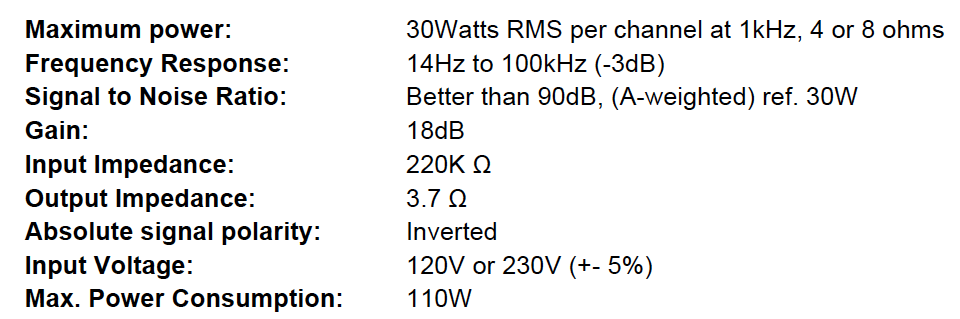
Amp 2 Crown PSA2  SS (actually have two...talk about silliness:))
 
Amp 3 Parasound 855a SS five channel but I will only use two.
 
Amp 4 Crown D-150(I can hear the cringing from here...lol) VERY SS...lol
 
Amp 5.  Some sort of Chip amp like the lm3887(or whatever it is, cant remember off hand)....SS, and I would still need to build it...lol
 
AMP 6  Even more out there...I have some VERY NICE car audio amplifiers, as well as a very powerful 12v supply (70A) that I use on my test bench for repairs and what not.  In the past I used it to drive a pair of Soundstream 10.0 "Class A" amps to a pair of Magnepan MgIIbs.  Sounded pretty good, also used some Denon car amps...and a slew of others(classics from the 1990's)...  Some of the high current amps have me curious.  The "cheater" amps rated at 50watts at 4 ohms, but would do 800watts if the impedance was driven low enough..usually 1ohm stable, 1/4ohm if actively cooled.  More silliness I know, just would like to get some ideas before I start liquidating the majority of my collection.....car, home, HT, and pro sound(mostly amps and speakers).....baaaad gas.  I know that a car amp seems silly but it could be battery powered, and some really do sound good, especially in the first watt, where I expect my headphones to stay.  I have other "outlets" for LOUD.....:wink:.  
 
FWIW I also have Parasound Speaker Switch that I plan to incorporate, eventually.  My custom speaker build has been put on hold. 
 
Thanks for any productive replies, your time is very much appreciated.  Obviously most concerned about the MV-50 tube amp, and was hoping someone had already successfully done one.  I am under the impression that the both the parallel and the series need to be used for tube amps.  It is el34 based, pretty sure common ground but will check when I unbox it...guess I could look at the schematics...heh.  But pretty sure it will be fine, I was thinking of going a little higher that 10 ohms, maybe 16 or so, depending on what is available.  Not really sure what to use for the "series" leg resistor though.  Help!?!
 
Oct 7, 2014 at 6:58 PM Post #2,756 of 3,871
What's the easiest (yet accurate) way to determine if a 75-Ohm "digital" cable is actually 75-Ohm?

(Armaegis graciously comes to my rescue in 3, 2, 1...)

:D


You would have to measure the Inductance and the Capacitance of the cable at the frequency of interest.
After that, there is a calculation which will give you the characteristic impedance. You can find it on Wiki.
But it won't matter in the real world......

Since your multimeter won't be able to measure capacitance and inductance......you are SOL.
 
Oct 7, 2014 at 7:13 PM Post #2,758 of 3,871
That 75 Ohm cable is more 75 Ohm than that other 75 Ohm cable?
:D
 
Oct 7, 2014 at 7:29 PM Post #2,759 of 3,871
I forgot to mention:

Characteristic Impedance is constant at high frequencies, I.e. video transmission, digital transmission. The cables impedance should match the impedance of the driving and and the receiving end of the circuit it is used in to avoid reflections. In addition, the wavelengths are very short at video and digital transmission frequencies.
Hence the term "Impedance Matching".

Characteristic Impedance varies at Audio Frequencies.
And the wavelength are very, very long in electrical cables at audio frequencies.
So we cannot and do not need to match the impedance of the cable to the impedance of the amp or the loudspeaker in an audio power amplifier circuit.

So there ain't no such thing as "Impedance Matching" in audio cables.
And don't nobody pull out no Maximum Power Theorem.
It's not used in the real world as it leads to poor efficiency.
 
Oct 7, 2014 at 9:59 PM Post #2,760 of 3,871
I forgot to mention:

Characteristic Impedance is constant at high frequencies, I.e. video transmission, digital transmission. The cables impedance should match the impedance of the driving and and the receiving end of the circuit it is used in to avoid reflections. In addition, the wavelengths are very short at video and digital transmission frequencies.
Hence the term "Impedance Matching".

 
OT, at very high frequencies (MHzs) if the transmitter is at 75 ohms and the receiver is at 75 ohms but the cable is below or above 75 ohms, is there a reflection? Is the reflection in voltage (which is force).
 

Users who are viewing this thread

Back
Top