Speaker amps for headphones
Dec 13, 2013 at 12:54 AM Post #1,876 of 3,871
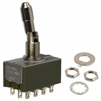
Hmmmm... It was an NKK DPDT switch that I didn't like. Diminished high frequency clarity and resolution compared to a reed relay. This was a silver plated copper contact version of the toggle switch. Maybe I should have gone good contacts?

Can you link the switch in question?
 
Dec 13, 2013 at 2:55 AM Post #1,878 of 3,871
Pfft, if you guys are going for versatility then just set up a rotary switch ladder attenuator that can simultaneously adjust the divider and output impedance. If you're sneaky you can do it all on one switch.


Dec 13, 2013 at 3:11 AM Post #1,879 of 3,871
  Pfft, if you guys are going for versatility then just set up a rotary switch ladder attenuator that can simultaneously adjust the divider and output impedance. If you're sneaky you can do it all on one switch.


Ahh, that would be exquisitely excessive lol 
wink_face.gif

 
Dec 13, 2013 at 3:20 AM Post #1,880 of 3,871
Oops, I meant rotary switch series stepped attenuator. Well, I guess both are doable depending how you jingle the wiring.
 
Dec 13, 2013 at 4:55 AM Post #1,881 of 3,871
Aw heck, why waste all that energy into resistors. Let's get into some autoformer shenanigans!
 
Dec 13, 2013 at 7:52 AM Post #1,882 of 3,871
Dec 13, 2013 at 11:14 AM Post #1,883 of 3,871
   
Who's Otto?

 
Octavius. Guy with eight arms. Also currently...
the new Superior Spiderman
(spoiler for those who read Marvel comics and haven't caught up in the past several months)
 
Dec 13, 2013 at 12:20 PM Post #1,884 of 3,871
Okay, so when you guys have designed truly magic boxes that automatically (or even manually, with safeguards) adjust attenuation, etc. depending on which amp is connected on on side and which cans are connected on the other... I'll buy one from whoever builds one that works, assuming the price is reasonable (a few hundred bucks?)
 
I'm waiting....
 
Dec 13, 2013 at 12:34 PM Post #1,885 of 3,871
   
Octavius. Guy with eight arms. Also currently...
the new Superior Spiderman
(spoiler for those who read Marvel comics and haven't caught up in the past several months)

 
What does he have to do with transformers? 
confused_face_2.gif

 
Dec 13, 2013 at 12:58 PM Post #1,887 of 3,871
  Here's the resistor network bypass switch details:
4PDT_switch2.jpg

4PDT_switch_terminals.jpg

Switch Up = Resistor Network Bypass. Switch Down = Resistor Network Active.
Lot's of soldering. . .

At first, something seemed amiss. However your wiring for 4-pin XLR is correct, I see that you went out of order on the L/R terminals. Did you do that for ease of wiring or something? One tip, if you haven't done this sort of thing before. Make a good mechanical connection of wire-terminal first, and then use a low melting point solder. I don't recommend using flux though, it could get really messy inside the switch.
 
Dec 13, 2013 at 1:30 PM Post #1,888 of 3,871
The pin order matches up with the box's speaker binding posts (actually it doesn't because I forgot to consider the switch is facing the opposite direction as the binding posts-I'll have to fix that).
 
Edit: fixed the switch pic.
 
Dec 13, 2013 at 1:35 PM Post #1,889 of 3,871
  The pin order matches up with the box's speaker binding posts (actually it doesn't because I forgot to consider the switch is facing the opposite direction as the binding posts-I'll have to fix that).

Don't forget to twist those corresponding pairs really good too! 
wink.gif
 
 
EDIT: Are you using a plastic or metal box for this? You may want to get some copper foil if plastic to at least provide a little shielding, and you can wrap it around the wires too.
 
Dec 13, 2013 at 2:01 PM Post #1,890 of 3,871
   
What does he have to do with transformers? 
confused_face_2.gif


Who's Otto?

 
Nothing really, but you asked about Otto... so I told you about Otto.
 
 
  Okay, so when you guys have designed truly magic boxes that automatically (or even manually, with safeguards) adjust attenuation, etc. depending on which amp is connected on on side and which cans are connected on the other... I'll buy one from whoever builds one that works, assuming the price is reasonable (a few hundred bucks?)
 
I'm waiting....

 
"simple" option: make the divider with a shunt-style stepped attenuator, maybe 3 steps at most (bypass, and two attenuation values), put the shunt on the bottom leg so that's your constant.
 
"is he serious?" option: wired in reverse... http://www.zeroimpedance.com/Zero-New.html
 
 
I still think y'all are drinking the kool-aid.
 

Users who are viewing this thread

Back
Top