Speaker amps for headphones
Dec 6, 2013 at 10:35 PM Post #1,831 of 3,871
  Hey, nice find!  Anyone know what they use to switch signals?  Relays, I'd expect.  Sealed, I'd hope.


  All switches will affect sound quality regardless of protection circuit - not just "some" ... especially if you are after a low-cost solution.

If you guys look at the Niles boxes compared to the OSD boxes, the insides and outsides are very similar. I'm thinking there is an OE supplier that is re-branding them. All i hear is praises for the Niles products, so I think it's a safe bet going with OSD. However, I (or Rob) will be the first to let you guys know if it sucks or not. I am getting one too :)
 
Dec 6, 2013 at 10:39 PM Post #1,832 of 3,871
   
 
If you guys look at the Niles boxes compared to the OSD boxes, the insides and outsides are very similar. I'm thinking there is an OE supplier that is re-branding them. All i hear is praises for the Niles products, so I think it's a safe bet going with OSD. However, I (or Rob) will be the first to let you guys know if it sucks or not. I am getting one too :)

Way to take one for the team!
 
Dec 6, 2013 at 10:56 PM Post #1,833 of 3,871
Dec 7, 2013 at 1:53 AM Post #1,835 of 3,871
   
Why? What exactly will a decent quality switch do to distort the signal?
 
se

I don't think you can get a decent quality switch that is also low cost, however "decent" is a subjective (and relative) term, so let's assume a switch that is objectively "a good switch".  My reasoning goes as follows:
 
It involves adding another component (and several solder joints), and likely different metal types (whether plated, stranded or solid), not to mention that in this case (a speaker switch box), it involves additional speaker cables to the box, additional cable connectors on the cables and as inputs and outputs from the box (and related solder joints) and, once again, presumably, disparate metal types.  Now, if somebody was to argue that none of these things distort the audio signal, they are free to do so, as my scientific basis is nil. Lots of people believe cables make no difference whatsoever, and you should just buy the cheapest possible.  People may believe the cheapest volume pots are equivalent to the most expensive (in this case there might be a greater scientific argument for some of the higher priced components than there is for "boutique switches"), but much of this is home-spun wisdom, mixed with the (likely questionable) assertions made by various audio companies, that every additional connection, wire, solder joint (LOL at "crimping connections") or disparate metal type will have a deleterious effect upon the signal and that everything should be kept as simple as possible, as minimal as reasonably allowable (heck, some manufacturers even claim that having straight traces on their circuit boards improves the sound quality !).  As to what specific distortion it causes, I have no idea.
 
For an example of this (possibly erroneous) thought process being taken to it's (il?)logical extreme, 47 Laboratory eschews any connectors on their speaker cable, preferring bare wire terminations (and people will argue endlessly about the different "sound" of Cardas solid 99.99999999999% pure copper RCA connectors versus Vampire Cryogenic Rhodium-Plated RCA connectors).  Even more impressively (quite ingenious really), 47 Lab designed a non-conductive Male "RCA" which also put the bare wire directly in contact with the female RCA's on their components (don't ask why they didn't find some way to eliminate the female RCA's on their components - perhaps they thought some crazy people might use other than their own approved wire to connect their components, and needed the compatibility).  Some people go to the extent of "hardwiring" their speakers or headphones to avoid additional contacts or connections claiming it improves the sound - though maybe this is a simple case of wishing to use the same type of wire inside as outside - and this may be predicated upon them having a similar geometry, rather than the same type of metal and avoidance of unnecessary connections etc.
 
All of which is a long-winded way of stating that I have no scientific basis for making such an assertion (and even if I did, I doubt I could explain exactly, or even approximately, what specific "distortions" were involved).  I could however, probably direct you to a good 100 pages worth of "advertising copy" from various audio companies with claims which sound scientific and logical and plausible  (to me), but whose "science" is probably ... well ... advertising copy ...
 
However, it sounds as though you might disagree ... or potentially disagree - hence your question.  I enjoy learning, and I respect your knowledge (which is undoubtedly far beyond mine in audio matters).  I would therefore be interested in hearing your opinion/s on the matter.  Have I been seduced by vagaries, misappropriations and various miscellania (or downright lies) ?  I would like to hear what your audio travels and travails have led you to believe/understand.  Don't stand on "politeness".  If you disagree, it may lead to the furtherance of my own knowledge and I would be grateful for that (if slightly egotistically "bruised" for a moment).  Thankyou. 
beerchug.gif
 
 
Dec 7, 2013 at 2:19 AM Post #1,836 of 3,871
   
 
If you guys look at the Niles boxes compared to the OSD boxes, the insides and outsides are very similar. I'm thinking there is an OE supplier that is re-branding them. All i hear is praises for the Niles products, so I think it's a safe bet going with OSD. However, I (or Rob) will be the first to let you guys know if it sucks or not. I am getting one too :)

 
Cool - please do let us know what you think of the switching box when you get it - it would come hugely in handy for me too !
 
Dec 7, 2013 at 6:53 AM Post #1,837 of 3,871

Resistor Network Interface With Switched XLR, 1/4" TRS and 1/8" TRS

The "Robinette Box" is a headphone to speaker amplifier interface box. It's designed to electronically match your headphones to a speaker amplifier's speaker output. Four resistors are used to give your amplifier its expected speaker load and to add attenuation to lower the amp's noise floor hiss and increase the useable volume knob movement.
The box features 1/4" (6.3mm) and 1/8" (3.5mm) Female TRS jacks for single-ended headphones and a Female 4-Pin XLR jack for balanced headphones. A toggle switch is used to switch between single-ended amplifiers and amplifiers with balanced output.

Robinette Box Schematic


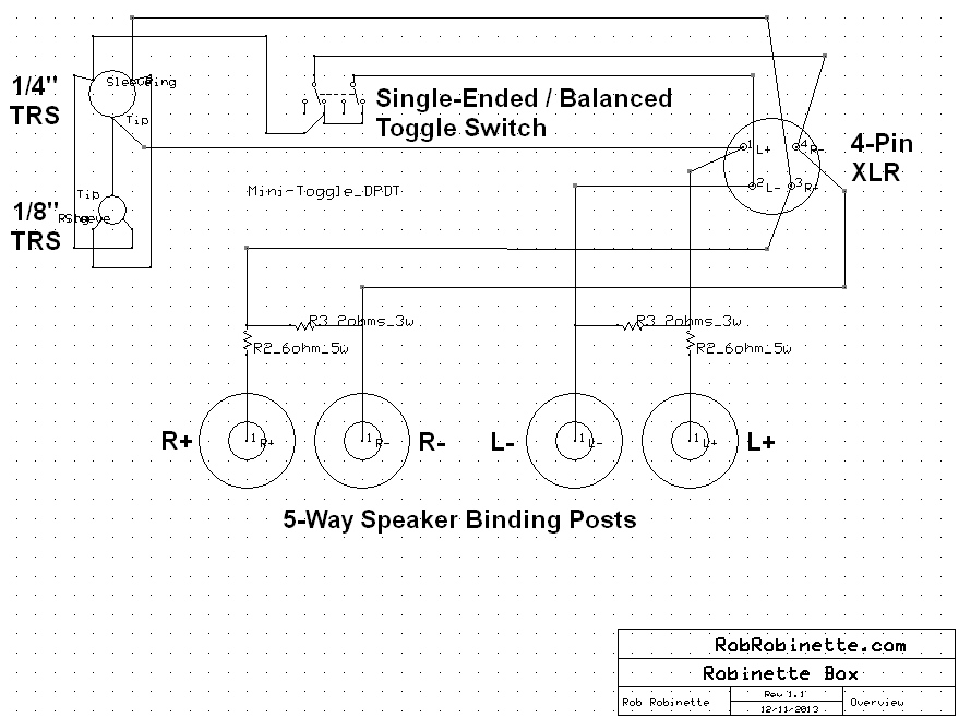
Toggle switch is shown in the "Single-Ended Amplifier" position with all three headphone jacks useable. With the switch in the other position, "Balanced Amplifier," only the 4-Pin XLR jack is useable. Download the Robinette Box ExpressSCH schematic file here.

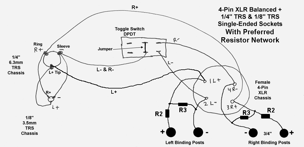
Robinette Box Detail

RobinetteBoxDrawing.jpg

Toggle switch toward XLR jack = balanced operation and only XLR jack is useable. Switch toward TRS jacks = single-ended operation with all three jacks useable. Note how the R- and L- are combined at the toggle switch with a jumper between the switch's center terminals.
WARNING: Only select TRS single-ended when connected to an amplifier that has its black speaker terminals tied together. You can verify this by using a multimeter's continuity function. With the amp unplugged ouch the multimeter's probes to the black speaker terminals. If you get the continuity beep your black speaker terminals are tied together and it's safe to use the TRS single-ended switch position.
 
Connection Detail
Left + Binding Post.....R2....R3....XLR Pin1....TRS-Tip (either one)....Other TRS-Tip
Left -  Binding Post.....R3....XLR Pin2....Switch Terminal1b---Switch Terminal2b....TRS-Sleeve (either)....TRS-Sleeve
Right - Binding Post....R3....XLR Pin4....Switch Terminal1a---Switch Terminal2a....Jumper to Terminal 2b to join Left -
Right + Binding Post....R2....R3....XLR Pin3....TRS-Ring (either)....TRS-Ring
This interface will connect just about any headphone with any amp (tube, solid state, balanced, single-ended). You can 
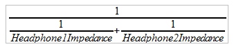
use the XLR and both TRS jacks simultaneously if connected to an amp with common ground output but they're wired in parallel so the circuit impedance will drop. The formula to determine what it drops to is:
 
2 Headphones Used Simultaneously
DualHeadphoneImpedanceFormula.jpg

With two 32 ohm headphones total impedance = 16 ohms
 
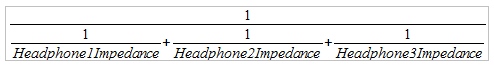
3 Headphones Used Simultaneously
TripplelHeadphoneImpedanceFormula.jpg

With three 32 ohm headphones total impedance = 10.7 ohms
 
Most likely the impedance drop will not have an appreciable effect on the amp or sound quality.
All of this will fit in a 4" x 5" x 1.5" project box. Put four 5-way speaker binding posts on one long side of the box (use 3/4" spacing for dual-banana plug compatibility). Red binding posts are +, black are -. Put the Female 4-Pin XLR chassis connector, 1/4" and 1/8" TRS chassis headphone jacks and DPDT (dual pole, dual throw) toggle switch on the other long side of the box. The R2 resistors should be long enough to make the connection from the + binding posts to the XLR connector without having to use additional wire. 18 to 22 gauge wire is recommended for the internal wiring. I made a set of 3 feet long speaker patch cables using 14 gauge speaker wire and banana plugs to connect the amp to the interface box but 16 or 18 gauge wire would work too.
 
Parts List
Project Box 4" x 5" x 1.5" or larger
Four 5-way Speaker Binding Posts
18 to 22 gauge wire
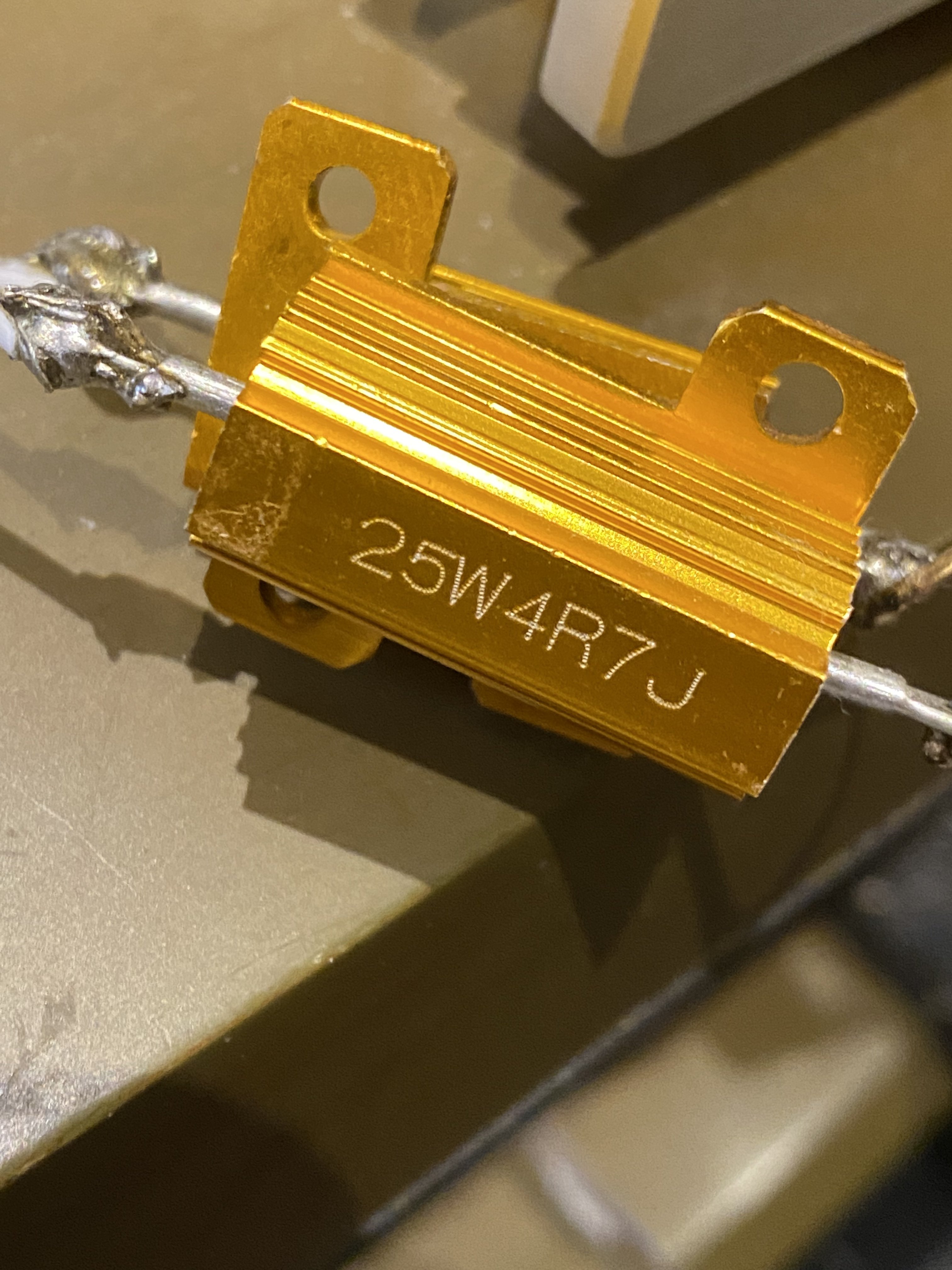
Vishay/Dale wirewound non-conductive resistors.
    2 each Resistor2 Mouser part# 71-RS0056R000FB12 Vishay part# RS0056R000FB12  5watts 6ohms 1%
    2 each Resistor3 Mouser part# 71-NS2B-2 Vishay part# NS02B2R000FB12  3watts 2ohms 1%
Female 4-Pin XLR Chassis Connector
Mini Toggle Switch DPDT (Dual Pole, Dual Throw)
1/4" 6.3mm Stereo TRS Chassis Connector (female, non-grounding)
1/8" 3.5mm Stereo TRS Chassis Connector (female, non-grounding)
 
I named this the "Robinette Box" after my ex-wife 
atsmile.gif

 
Rob
 
Dec 7, 2013 at 12:18 PM Post #1,842 of 3,871
  Can anyone explain the pros and cons of using RCA attenuators at the input of the amp such as the one below instead of a resistor network at the output of the amp? Would these lower the noise floor of an amp?

http://www.head-fi.org/products/goldenjacks-attenuators-20db

No.  They attenuate the input signal.  They will not lower the noise floor, because the noise floor is a contribution from the amp itself, not the source.  Source noise is a different issue, and these won't help that, either.  The application for these devices is if you have a source with output signal too large for the amplifier (or whatever other components you are trying to connect).
The resistor network on the output reduces the signal amplitude (voltage) delivered to the load (headphone, for example).  It reduces the apparent noise floor of the amplifier because it is attenuating the signal.  The noise that is heard is typically from the gain stage(s) of the amplifier.  Since the gain is fixed, that noise is fixed.  Attenuating the output of the amplifier allows you to feed in a larger input signal for a given SPL out.
 
Dec 7, 2013 at 12:40 PM Post #1,844 of 3,871
Thanks potterma, I currently have 20*log(Rh/(R2+Rh)) which gives a negative number. It just seemed like R1 would add some attenuation, thanks for the clarification.


R1 draws current from the amplifier, but that's it. Of course it would be useful for amps that want to see a nice stable load.
 
Dec 7, 2013 at 1:13 PM Post #1,845 of 3,871
  No.  They attenuate the input signal.  They will not lower the noise floor, because the noise floor is a contribution from the amp itself, not the source.  Source noise is a different issue, and these won't help that, either.  The application for these devices is if you have a source with output signal too large for the amplifier (or whatever other components you are trying to connect).
The resistor network on the output reduces the signal amplitude (voltage) delivered to the load (headphone, for example).  It reduces the apparent noise floor of the amplifier because it is attenuating the signal.  The noise that is heard is typically from the gain stage(s) of the amplifier.  Since the gain is fixed, that noise is fixed.  Attenuating the output of the amplifier allows you to feed in a larger input signal for a given SPL out.

@manbear This right here. Further, those RCA attenuators are really the last thing you want to do. What you really want to do in your case is lower the gain of the amp, if you can't do that, then I suggest you may have the wrong amp for your drivers. If you have no other way possible then those are the way to go. You may also have a really hot signal voltage (uncommon unless it's from a hot preamp) that the amp can't handle, in which case you could switch DACs. Wasting so much signal voltage is a sad thing 
frown.gif


Users who are viewing this thread

Back
Top