pupDAC Step-by-Step Build Thread
Jan 27, 2013 at 2:44 PM Post #62 of 359
I got my first problem sorted. Now, the computer recognizes it and powers the LED. I'm getting pretty close to the right voltages everywhere except where the 4V5, I'm getting 0, and at -2V5, I'm getting -.7
 
Thoughts?
 
Jan 27, 2013 at 5:26 PM Post #63 of 359
I reflowed virtually everything on the board. I've got the -2.5 now. Still ~0 at the 4.5 test point. Also, all of the 5V/-5V points are actually at ~4.8/~-4.8V. Is that close enough?
 
The 4.5V point is killing me, I've reflowed everything!
 
Jan 27, 2013 at 6:10 PM Post #64 of 359
Quote:
I reflowed virtually everything on the board. I've got the -2.5 now. Still ~0 at the 4.5 test point. Also, all of the 5V/-5V points are actually at ~4.8/~-4.8V. Is that close enough?
 
The 4.5V point is killing me, I've reflowed everything!

Yes - the 5V values depend on your PC's power supply.  However, if there's a short, the voltage could sag a bit.
 
Check the schematic and the board layouts on the pupDAC website.  U5 only has L4 in its direct path.  The rest of the stuff are capacitors to ground: C20, C21, C23, C2, and C16 - alsot C6 and C17.
 
I'd look carefully at U5 is soldered and L4, but it's only a guess without pics.
wink.gif

 
Jan 27, 2013 at 8:25 PM Post #65 of 359
Quote:
Quote:
I reflowed virtually everything on the board. I've got the -2.5 now. Still ~0 at the 4.5 test point. Also, all of the 5V/-5V points are actually at ~4.8/~-4.8V. Is that close enough?
 
The 4.5V point is killing me, I've reflowed everything!

Yes - the 5V values depend on your PC's power supply.  However, if there's a short, the voltage could sag a bit.
 
Check the schematic and the board layouts on the pupDAC website.  U5 only has L4 in its direct path.  The rest of the stuff are capacitors to ground: C20, C21, C23, C2, and C16 - alsot C6 and C17.
 
I'd look carefully at U5 is soldered and L4, but it's only a guess without pics.
wink.gif


I'm getting 4.7V there, but no sound...may be time for some pictures. I'm going to try to reflow the DAC again, then I'll post pics if that doesn't fix it.
 
Jan 27, 2013 at 9:36 PM Post #67 of 359
Well, honestly -  U1 and U3 don't look too bad from the photo's perspective.  I can't tell about the right side of U3, though.  You know that you can remove C9 and C10 if you have to, to get at the pins on the right side of U3.  I've done that before.
 
However, U5 looks suspect.  Try to refer to the "drag and wipe" method on the pupDAC website - http://www.diyforums.org/PupDAC/PupDACsolder.php
With a clean soldering iron, see if you can clean up those pins.  That might help.  L4 looks pretty bad, too.  It's quite possible that you have a short there.  If need be, remove the ferrite entirely and re-solder it, starting fresh.  You can melt one end while holding an X-acto knife under the ferrite, pulling it up.  Once you get one end up away from its pad, then you can melt the other end and pull it off.  Clean up with some de-soldering braid, and you can start completely fresh.
 
Good luck and let us know how it goes!  
 
Jan 27, 2013 at 9:44 PM Post #68 of 359
Sorry for the mediocre pictures. I'll give it a try later tonight. iI think the issue is on the day chip, not the usb chip, because it's being recognized, and the voltages are close, it just won't play. I'll try all of your suggestions and report back.
 
Jan 27, 2013 at 11:54 PM Post #70 of 359
In all my hacking, I cooked the end right off of C11. Oh well, it's just a bypass cap, it should work even without C11. We shall see.
 
Thought the short was there, but nope, not there. I'm running out of ideas.
 
Jan 27, 2013 at 11:59 PM Post #71 of 359
There is about 25 ohms from the IOR+, IOR-, IOL+, IOL- to ground, is that right? It seems awfully low.
 
Also, could it just be the copious amounts of wet flux on the board?
 
I'm also getting 0V on one of the 3.3V pads now. SO FRUSTRATING!
 
Jan 28, 2013 at 7:36 AM Post #72 of 359
Quote:
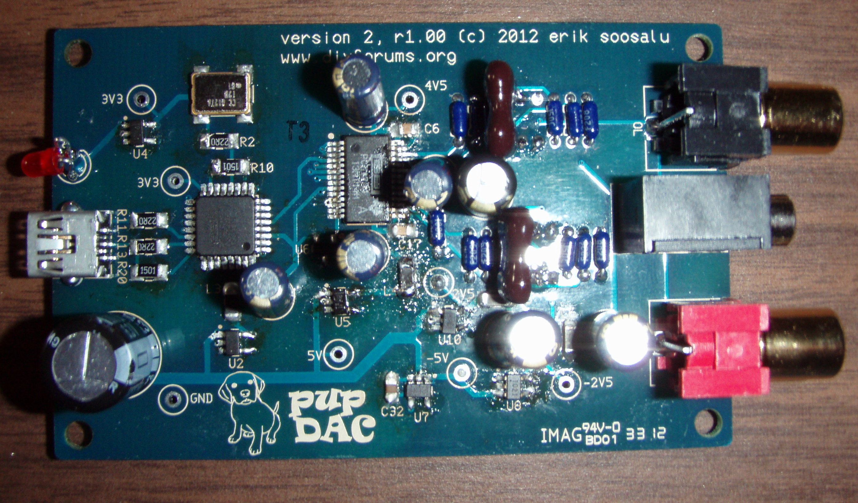
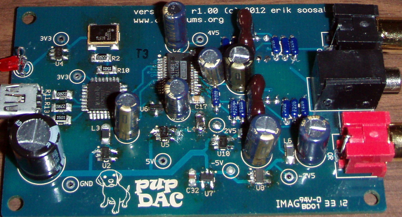
Check U5 (it comes from there), then check L4

aha! that was it. Now my only problem is left channel distortion and right channel not really sounding loud at all. 
 
Jan 29, 2013 at 9:43 AM Post #73 of 359
I need to order some new caps. While I'm ordering, I want to take care of any other stuff I might need. Has anyone directly compared the OPA2835 and the OPA2836? Does the difference in bandwidth and output current really make any difference?
 
May 20, 2013 at 8:24 PM Post #74 of 359
So, I built mine tonight.  Although the LED lights, it won't install.  Using my keen troubleshooting skills and my increasingly poor soldering techniques (as it turns out, frustration is directly proportional to Gin & Tonics, which is aggravatingly inversely proportional to quality of work), I managed to fix a few cold joints, but I have one remaining problem:  U4 is outputting 1.3V vice 3.3V.  I re-flowed U4, C4/C5/C7, to no avail.  I also re-flowed C1 and X1.  
 
Is it possible that I damaged U4 (or some other component) with too much heat?  I didn't use heatsinks.  I have a pretty damn good soldering unit (PACE MBT), and used good flux/solder (Kester liquid pen, and eutectic).  The only time I thought I maybe had heat on for too long was when a capacitor stuck itself to the iron, causing me to frantically shake it off onto the table.  
 
Also, yes, the solder globs are horrendous, as is the board cleanliness.  I blame the macro lens for capturing entirely too much detail.
 
Any help is appreciated, thanks!
 
https://plus.google.com/photos/111881888765532210244/albums/5880217591828488561
 
May 20, 2013 at 10:36 PM Post #75 of 359
Quote:
In all my hacking, I cooked the end right off of C11. Oh well, it's just a bypass cap, it should work even without C11. We shall see.
 
Thought the short was there, but nope, not there. I'm running out of ideas.

When using very fast opamps, correct bypassing is absolutely necessary, not optional.


There is about 25 ohms from the IOR+, IOR-, IOL+, IOL- to ground, is that right? It seems awfully low.

It's a passive I/V stage consisting of a 22 ohm resistor to ground. So it should read 22 ohms.
Current output DACs want to see a 0-ohm load ideally.
 

Users who are viewing this thread

Back
Top