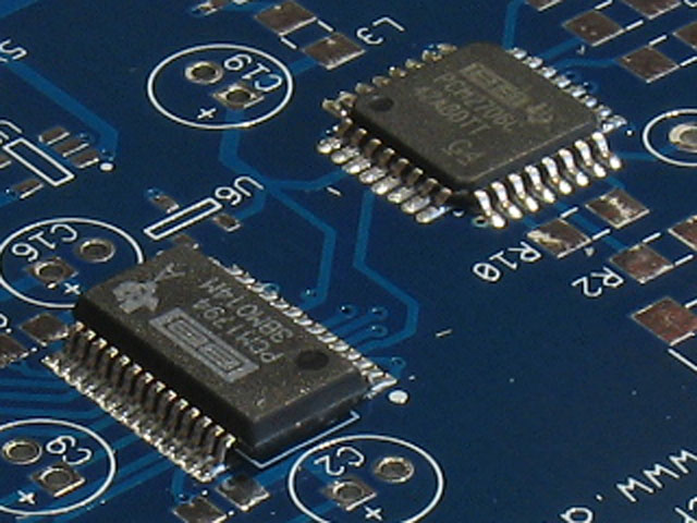
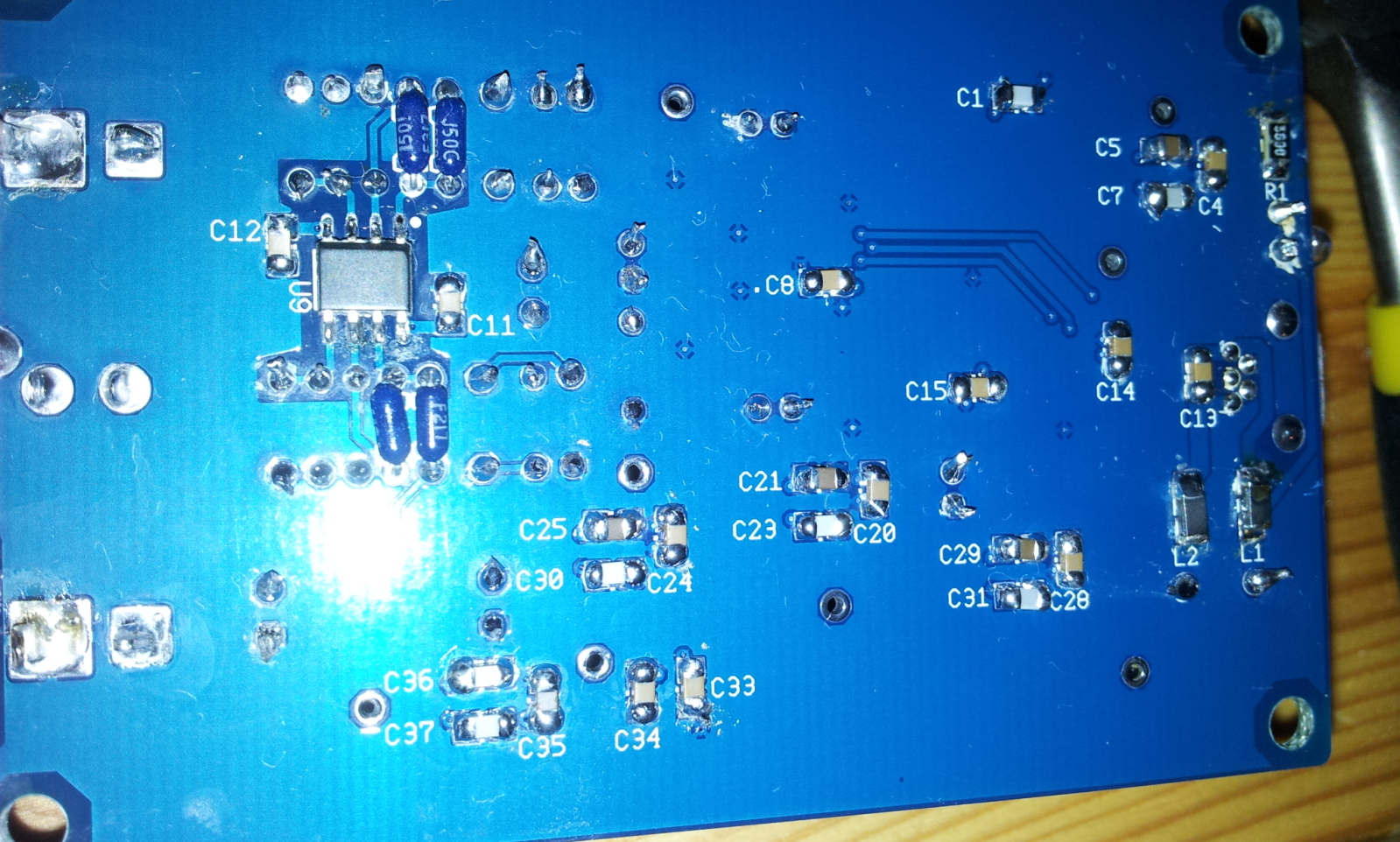
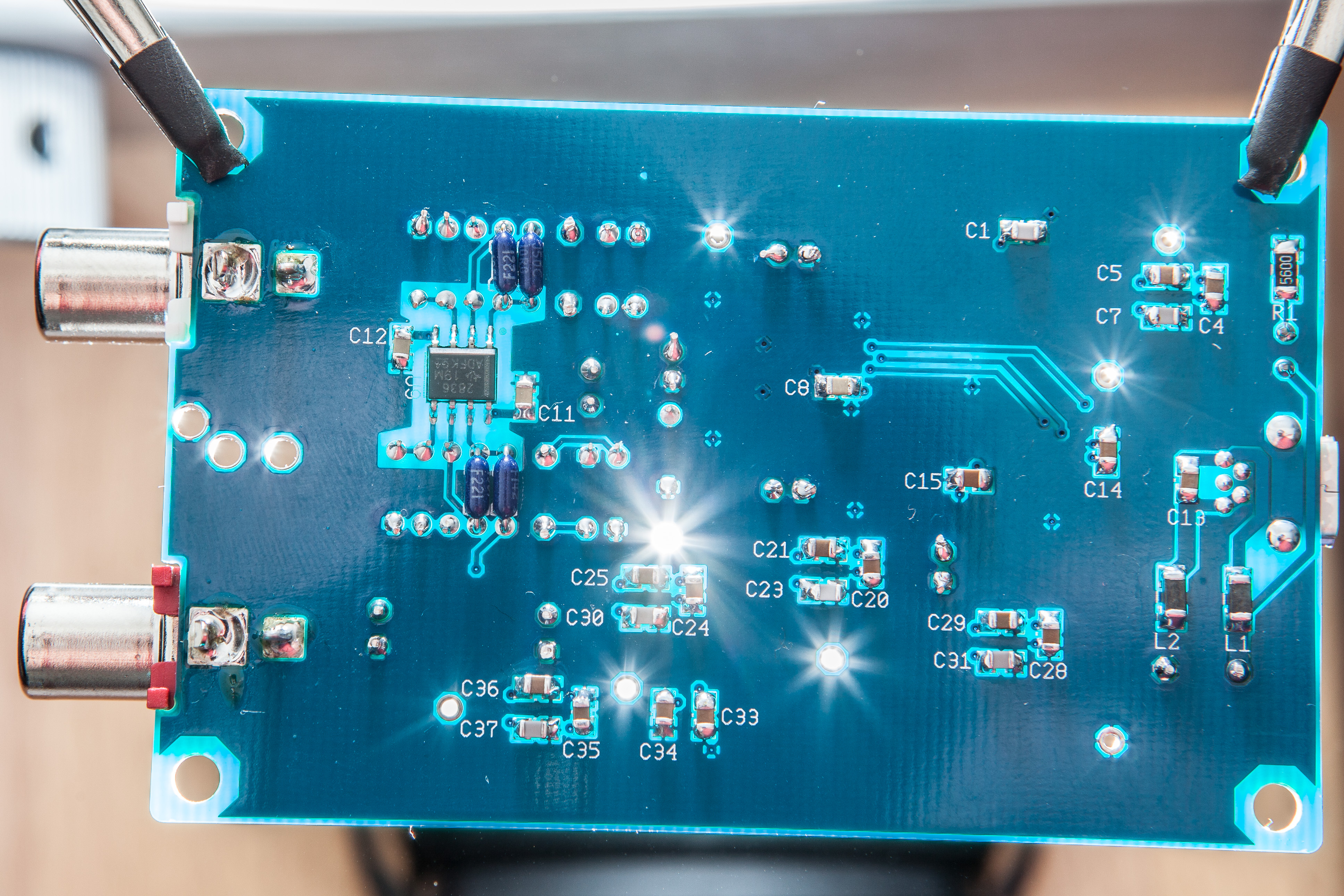
looks like there may be a few cold joints there.
Tomb, perhaps you might consider including a small roll of good solder, a small tube of flux and possibly a roll of solder wick with these kits?
Personally I don't know how I ever did SMD work without good flux (I like the stuff that chip-quick sells, but it is not cheep).
I know it would add to the cost of the kit, but i think in the long run it would be worth it.
No offense, but these things are emphasized quite strongly - here and here and here and finally - in the very first post in this thread: here . No offense, but most of us draw the line at putting construction tools in a DIY kit. Might as well include the tweezers and a Hakko 936, next. I guess I'm a bit miffed at the implication that I haven't provided enough support for Beezar kits.
Kyoshiro, I don't know where you are located, but see if you can get some flux (i prefer a gel type for SMD work) and some small (1/8 to 3/32 inch) solder wick before you "re-flow" your board.
I would coat every joint with a little flux, then heat it with the iron till it melts and turns shiny, then remove the heat. Use the solder wick to pull up excess solder if needed.