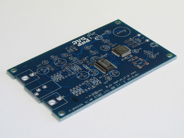
Hello Everyone,
I just finished soldering my Pupdac! It sounds great! There's only one problem... The volume cannot be adjusted. I read earlier in this thread that someone had the same issue, but it wasn't clear to me how they fixed it.
The problem:
- Windows volume control does not have any effect on volume output to my HD599s
- Volume is very loud.
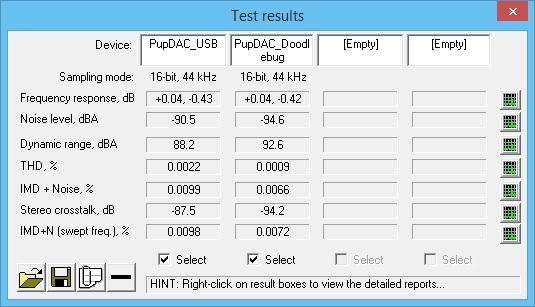
Some diagnostic info:
- The board is detected as: "3- USB AUDIO DAC"
- Windows volume bar can be adjusted but has no effect.
- Volume can be reduced through applications such as Spotify and YouTube.
- Music sounds great with reduced volume from applications with internal volume control.
- No noise can be heard when nothing is playing.
- Test Pad voltages
- Test Pad 3.3V-1 = 3.294V
- Test Pad 3.3V-2 = 3.287V
- Test Pad 5V = 4.940V
- Test Pad -5V = -4.923V
- Test Pad 4V5 = 4.746V
- Test Pad 2V5 = 2.496V
- Test Pad -2V5 = -2.499V
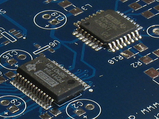
After some reading of the PCM2706C datasheet, it seems as though it is operating in its default control interface. In which, the spdif output to the PCM1794A is not volume controlled? Is my reading of that correct?
" The master volume control is not supported. A request to the master volume is stalled and ignored. " (Section 9.5.1.2 - Ti PCM2706C datasheet).
Where should I look next for fixing this issue?
Thanks in advance for the help
")