pupDAC Step-by-Step Build Thread

Jan 21, 2013 at 9:40 AM Post #46 of 359
Quote:
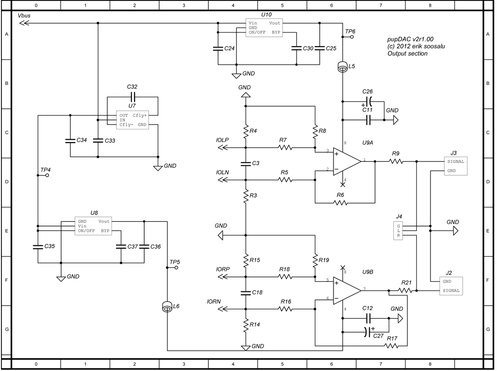
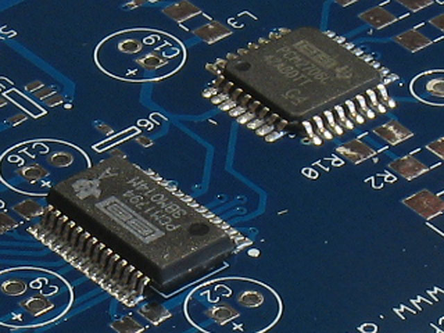
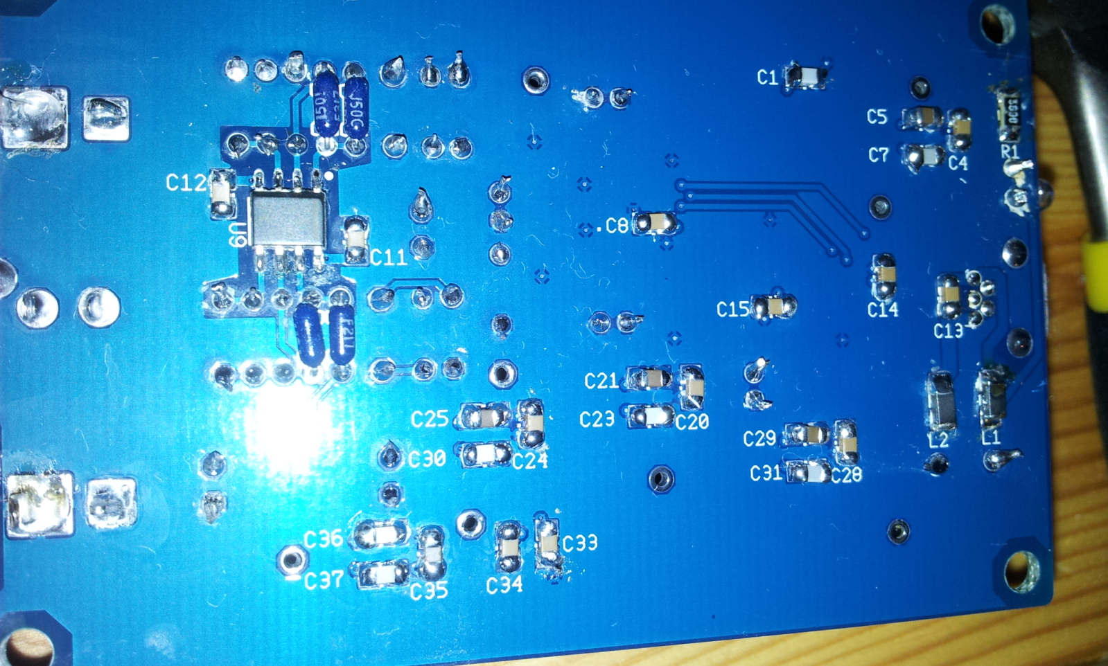
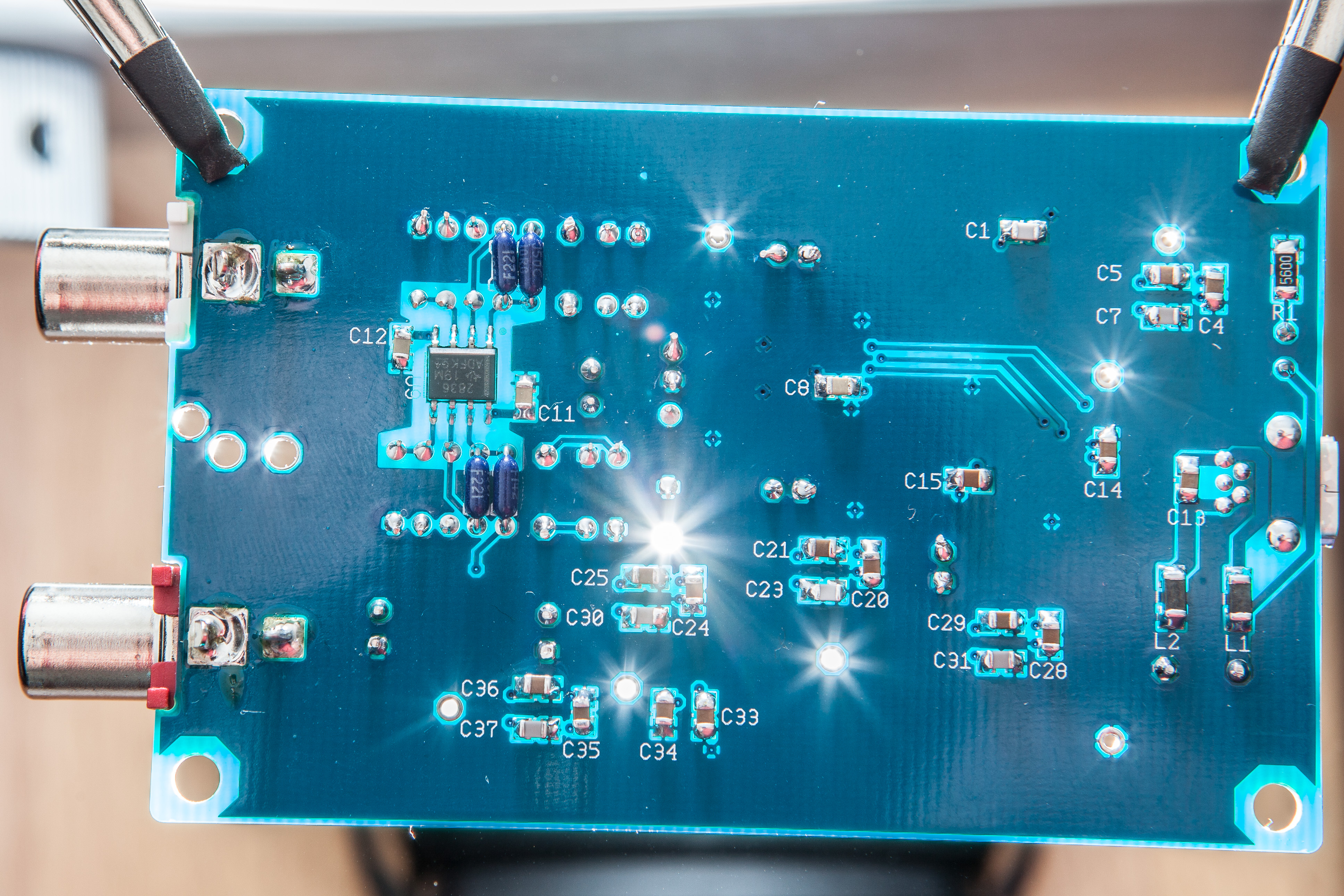
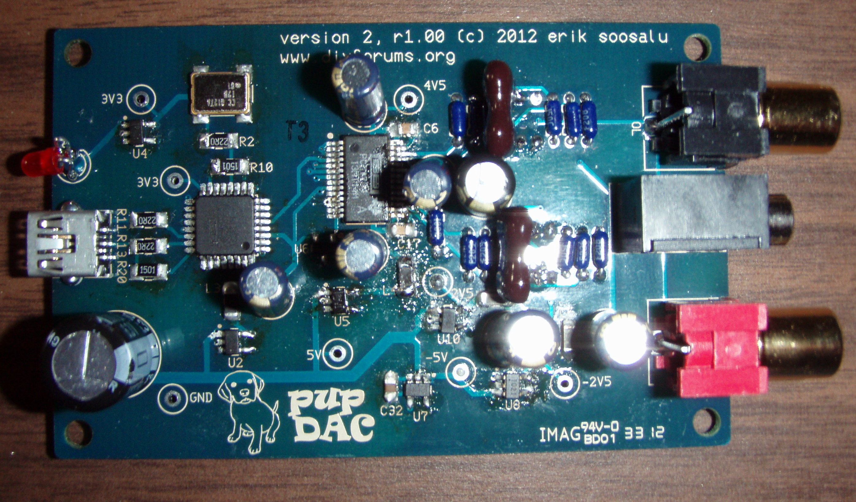
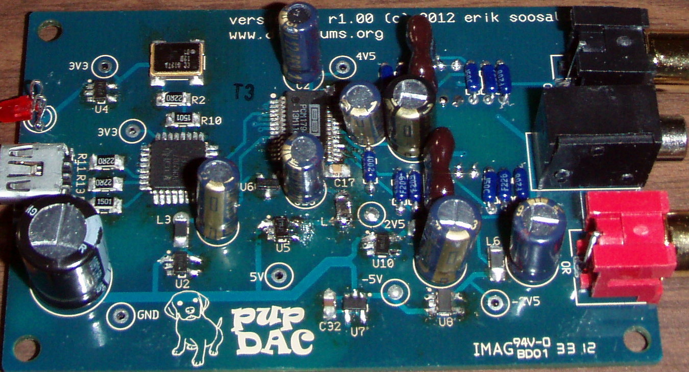
I'm using some 60/40 solder that I had lying around that I bought for soldering the O2, thought it would do the trick nicely as my other roll is a WBT lead-free.  But yeah first time soldering SMDs so need a bit more work here n there. I still havent had time to take the steps suggested as I have caught a cold, should get to it soon enough. Thanks for all the suggestions tho!

Well, we're here when you're ready.  They were all good suggestions and Kim has pointed out a couple of trouble points you may want to check when you're feeling better.
smily_headphones1.gif

 
Jan 24, 2013 at 4:55 AM Post #48 of 359
Quote:
Got over the cold yet and had any chance to do those measurements, etc.?

Will get to it this weekend. Giving a training session tomorrow and have been hard at work preparing for that and other things for my current project. (I work in the IT Sector) But yes, may even get to it tomorrow night :) 
 
Jan 25, 2013 at 10:28 AM Post #49 of 359
gnd to 3v3 next to oscilator is 3.28V
gnd to pcm's 3v3 is 3.32v
gnd to 4v5 is 0
gnd to -5v is only .3v
gnd to -2v5 is 0
 
Jan 25, 2013 at 10:45 AM Post #50 of 359
welll, reflowed u3's pins that arent obstructed and it installs lol
 
Jan 25, 2013 at 11:11 AM Post #51 of 359
Quote:
welll, reflowed u3's pins that arent obstructed and it installs lol

Well, that's good news!
 
Does it completely work?  You had several voltages messed up, but some shorting pins could cause some of that.
 
Jan 25, 2013 at 11:25 PM Post #54 of 359
Quote:
Well, that's good news!
 
Does it completely work?  You had several voltages messed up, but some shorting pins could cause some of that.

 
nope :( 
Get hissing on LEFT channel and nothing on right channel. I probably gotta sort out those voltages
 
Jan 26, 2013 at 6:27 AM Post #55 of 359
partially tried to reflow the other side of u3
 
only 4v5 is reading 0 now.... grrr
 
Jan 26, 2013 at 8:18 AM Post #57 of 359
Quote:
What does the +5V test point read?
If it's too much lower than 5V, this may be an issue with the 4.75V reg.

5.03V so don't think its this regulator
 
Jan 26, 2013 at 10:34 PM Post #59 of 359
Quote:
I seem to be getting no power from the USB. I have no idea why.

Sorry to hear it, scootsit - do you have some pics of the PCB you can share?  Just some info - the USB connection is fairly straightforward.  If the LED doesn't light, it's pretty much the USB connector pins or some soldering issues with L1 and R1.
 
Jan 27, 2013 at 2:01 AM Post #60 of 359
Quote:
Quote:
I seem to be getting no power from the USB. I have no idea why.

Sorry to hear it, scootsit - do you have some pics of the PCB you can share?  Just some info - the USB connection is fairly straightforward.  If the LED doesn't light, it's pretty much the USB connector pins or some soldering issues with L1 and R1.


I really gobbed the solder onto the USB jack to be sure it doesn't pull off the board. There's definitely a short somewhere between V+ and ground, it's probably in there. I'm going to fix it tomorrow. If I can't, then I'll post pictures. A few of the USB pins seem to all be connected, so I'm assuming there's a clump of solder stuck under it. Thanks for the offer, though!
 

Users who are viewing this thread

Back
Top