pupDAC Step-by-Step Build Thread
May 23, 2013 at 9:34 PM Post #76 of 359
Quote:
So, I built mine tonight.  Although the LED lights, it won't install.  Using my keen troubleshooting skills and my increasingly poor soldering techniques (as it turns out, frustration is directly proportional to Gin & Tonics, which is aggravatingly inversely proportional to quality of work), I managed to fix a few cold joints, but I have one remaining problem:  U4 is outputting 1.3V vice 3.3V.  I re-flowed U4, C4/C5/C7, to no avail.  I also re-flowed C1 and X1.  
 
Is it possible that I damaged U4 (or some other component) with too much heat?  I didn't use heatsinks.  I have a pretty damn good soldering unit (PACE MBT), and used good flux/solder (Kester liquid pen, and eutectic).  The only time I thought I maybe had heat on for too long was when a capacitor stuck itself to the iron, causing me to frantically shake it off onto the table.  
 
Also, yes, the solder globs are horrendous, as is the board cleanliness.  I blame the macro lens for capturing entirely too much detail.
 
Any help is appreciated, thanks!
 
https://plus.google.com/photos/111881888765532210244/albums/5880217591828488561

I apologize, I've been busy at my day job with a big project - just got it finished today.
 
Just MHO, but looking at your pics, it seems the solder joints are still too cold.  It's sometimes better to have higher heat and less overall contact.  IOW, high heat may allow you to quickly heat the solder and secure the joint, then remove the iron much faster than if you were using a colder temp.  Of course, moderation is key: it's very easy to turn the temps up where the chips die a fast death.
 
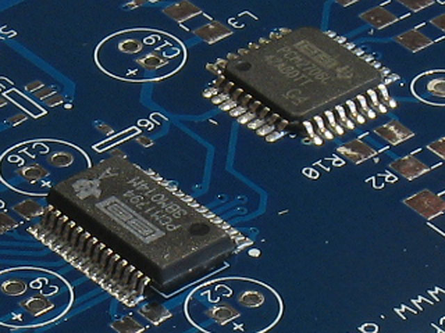
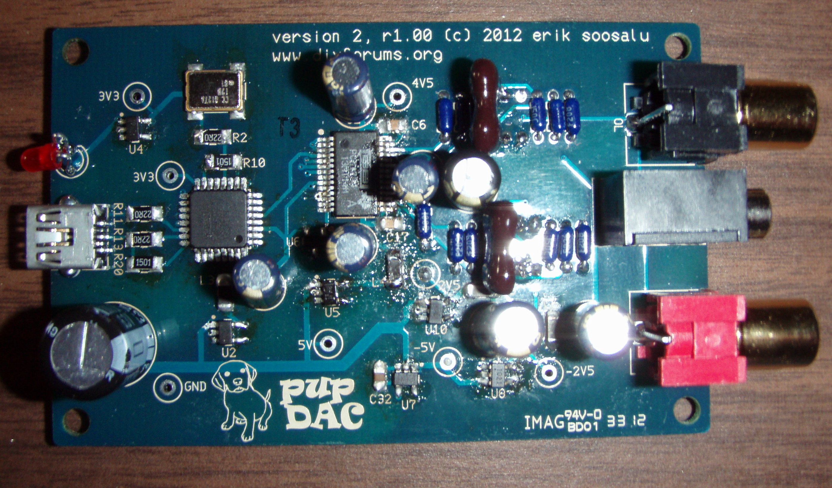
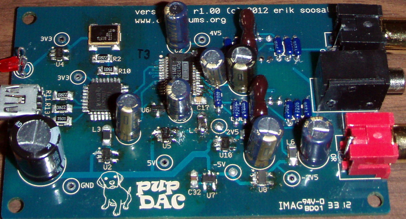
Still, I would turn the heat up some (50 degrees F.?) and see if you can reflow those joints around X1 and U4.  Can't tell from the pics, but keep in mind that the X1 crystal will be shorted out if you get an solder on the top metal cap.  Other than that and re-flowing U4 to ensure there are no bridges, you may need to check U1, the PCM2707 chip.  If you can't get a connection - once the U4 is measuring correctly - then you may need to look at the U1 and U3 chips. If those chips have issues, it can translate through the rest of the circuit to even make the regulators supply less voltage.  Things are inter-connected, IOW.
 
Good luck and let us know what turns out from your troubleshooting! 
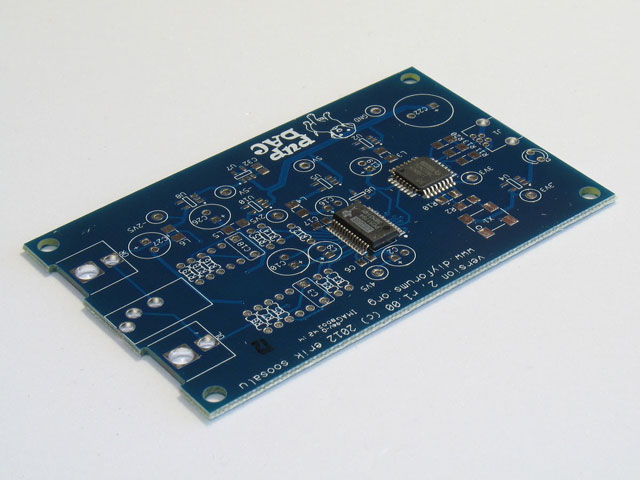
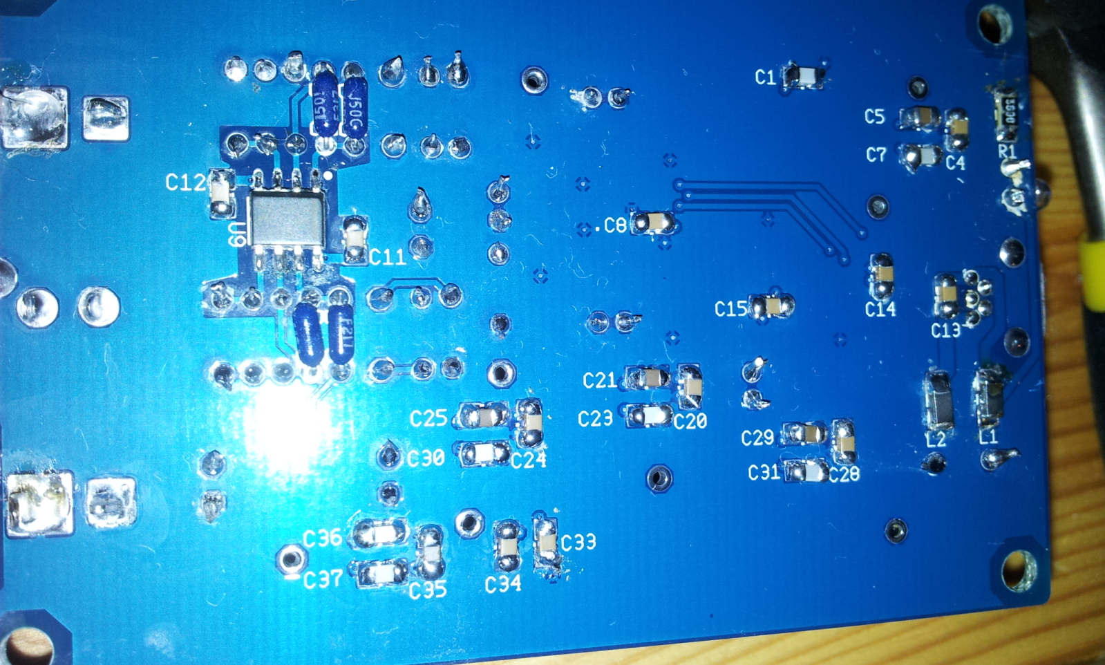
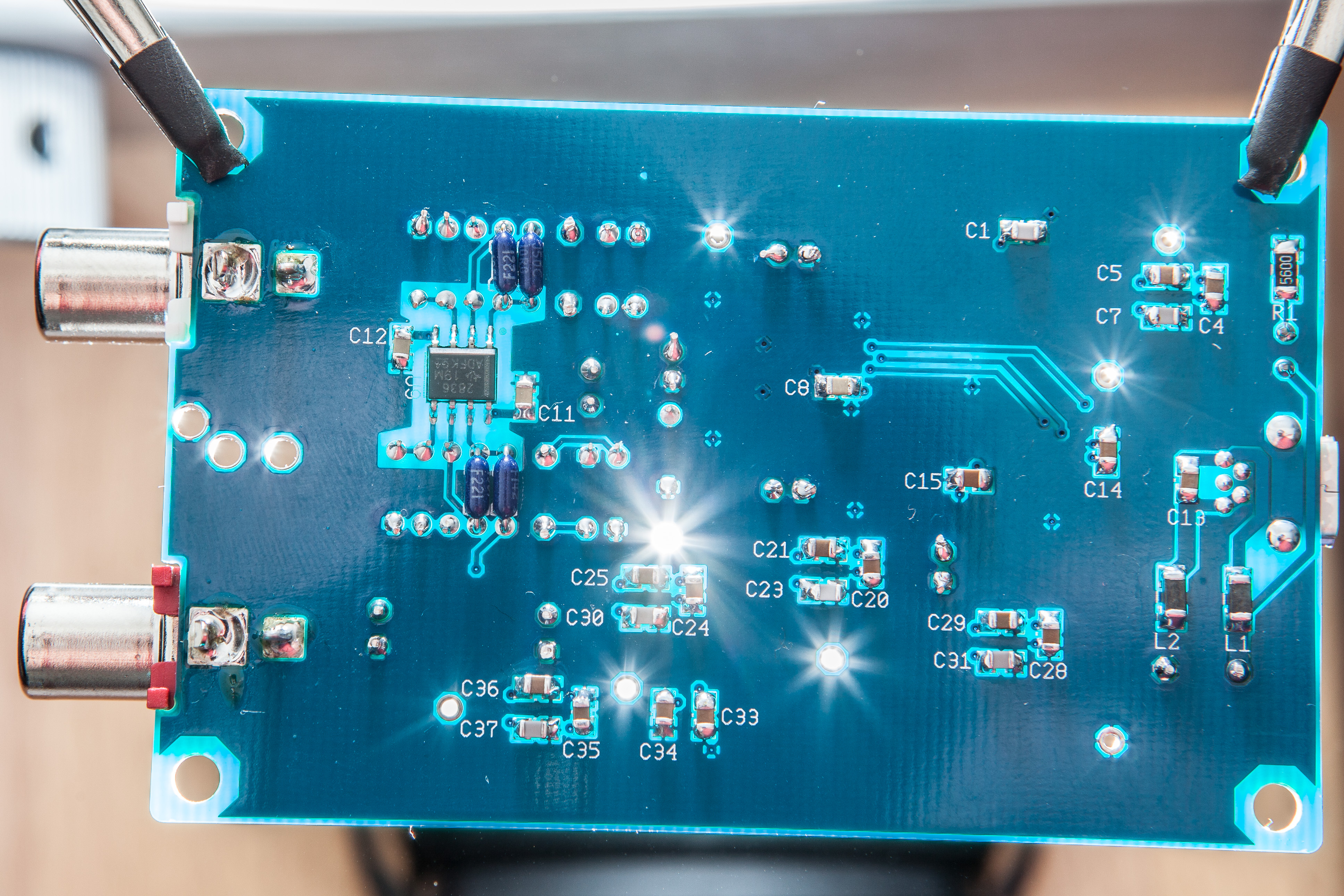
 
Jun 1, 2013 at 10:58 AM Post #77 of 359
Hi,

I purchased a pubDAC and soldered everything. It seems to be recognized ( I attached some console output), but neither under windows nor under arch linux I get some sound out of the board. Neither headphone jack nor RCA jacks give me something. I measured the testpoints as suggested on the page. 4V5 gives a little bit too much, Also the RCA Jacks have a bit too much Voltage.

Any suggestions where I should start? Thanks for your advice guys!

Kind Regards,
Jo


3V3 - 3.29V
3V3 - 3.27V
5V -  5.02V
-5V - -5.01V
2V5 - 2.47V
-2V5- - -2.48V
4V5 - 4.73V

GND->OL 4.5mV
GND->OR 3.2mV

 
Console Output: http://pastebin.com/aTEryZYg
 
Jun 1, 2013 at 1:52 PM Post #78 of 359
Quote:
Hi,

I purchased a pubDAC and soldered everything. It seems to be recognized ( I attached some console output), but neither under windows nor under arch linux I get some sound out of the board. Neither headphone jack nor RCA jacks give me something. I measured the testpoints as suggested on the page. 4V5 gives a little bit too much, Also the RCA Jacks have a bit too much Voltage.

Any suggestions where I should start? Thanks for your advice guys!

Kind Regards,
Jo


3V3 - 3.29V
3V3 - 3.27V
5V -  5.02V
-5V - -5.01V
2V5 - 2.47V
-2V5- - -2.48V
4V5 - 4.73V

GND->OL 4.5mV
GND->OR 3.2mV

 
Console Output: http://pastebin.com/aTEryZYg

4.73 is fine for the 4V5 point.
 
The rest obviously looks OK, too (except the output offset).  It could be in the DAC chip itself (on the output side) or the opamp on the bottom of the PCB.  So ... it sounds like we need some pics. 
 
Jun 2, 2013 at 6:39 AM Post #79 of 359
Hi,
 
It was the first time I did some SMD soldering, so don't be upset with the results. I resoldered U9 on the backside, but it didn't help. I did't want to touch the chips on the front side without your advice, because I had a lot of trouble soldering them (which you can see on the right hand side of PCM1794). Therefore I used a minimum amount of solder on the left side, but I measured through the legs at the top to their corresponding contact point somewhere else on the board and they "seemed" to have contact. If you say I should solder them again I will do so, but I did not want to make a bigger mess than it already is. Hope the picture quality is good enough, I didn't get them "sharper".
 
Thanks for you help guys!
 
 
https://imageshack.us/a/img690/8963/img20130602121140.jpg
https://imageshack.us/a/img208/6914/img20130602121204.jpg
 
Jun 2, 2013 at 9:49 AM Post #80 of 359
Quote:
Hi,
 
It was the first time I did some SMD soldering, so don't be upset with the results. I resoldered U9 on the backside, but it didn't help. I did't want to touch the chips on the front side without your advice, because I had a lot of trouble soldering them (which you can see on the right hand side of PCM1794). Therefore I used a minimum amount of solder on the left side, but I measured through the legs at the top to their corresponding contact point somewhere else on the board and they "seemed" to have contact. If you say I should solder them again I will do so, but I did not want to make a bigger mess than it already is. Hope the picture quality is good enough, I didn't get them "sharper".
 
Thanks for you help guys!
 
 
https://imageshack.us/a/img690/8963/img20130602121140.jpg
https://imageshack.us/a/img208/6914/img20130602121204.jpg

I can't find anything amiss, except around the bottom right of the DAC chip.  At least from these photos, it appears you did very well, indeed, for a first time soldering SMD!
 
Here's the situation - if a PC recognizes the device, but no sound output occurs, and all the voltages check out, then there has to be an issue in three possible places:
  • Connections between the PCM2707 and the PCM1794,
  • Connections from the output (analog music) side of the PCM1794, or
  • Connections from the analog (music) output of the pupDAC.
 
Of these, I would ordinarily tend to discount #1.  The reason being, first - your solder work looks fine on the PCM2707 chip and on the left side of the PCM1794.  Second, chances are if there was some issue in the connection between the two DAC chips, the PCM2707 would show some sort of error, too, and not be fully recognized by a PC.
 
That said, one might make the case there's a fundamental issue with the connections between the two PCM chips.  Otherwise, you might get partial sound, static, or some other indication of an incomplete connection.  If you can't hear anything anywhere, then the issue may be more fundamental and it could be the connections between the PCM chips.  There are four of those - one is quite obvious and is the trace from the 4th pin from top right on the PCM2707 to the 4th pin from top left on the PCM1794.  The other three pass through vias to the bottom of the PCB and then connect to the left side of the PCM1794.  These pins are the first 3 pins on the top left of the PCM2707 and they connect to the 5th, 6th, and 7th pins from top left of the PCM1794.  IOW, the 4th, 5th, 6th, and 7th pins from top left on the PCM1794 are all of the connections between the PCM2707 and PCM1794.  Check those pins with your DMM and see if you can measure -0- resistance between them and their corresponding connections to the PCM2707.  If not, then you may need to re-flow the PCM1794 pins and even the PCM2707 chip, even though it looks good from the photos.
 
That leaves either #2 or #3.  I would ordinarily discount #3, because it appears the soldering you've done on the opamp looks fine.  Certainly, there's plenty of room around the pins to determine whether you've got good connections or not.  If you can verify the traces from the tops of the pins to the traces, then I don't think there's an issue.  Still, it would help to check every SMD part.  Remember that capacitors left unsoldered may affect performance, but I doubt seriously they would cause the device not to work.  Resistors and ferrites, on the other hand, have to be soldered on both sides or there is an actual break in the circuit.
 
If nothing else checks out so far, then that leaves the right side of the PCM1794 chip.  It's hard to tell for sure, but there may be a bridge between the bottom two pins on the right side.  If that checks out OK (look for zero resistance between the two pins to confirm a bridge), then verify connection from the pins to the traces for the most important pins for the audio output - the 3rd and 4th pins from the top right, and the 3rd and 4th pins from the bottom right.  Those pins are the balanced current outputs for the Left and Right channels of the DAC.
 
One thing to look for when you measure with the DMM - it may be that you're pressing down on the DAC pin and the force is enough to make the pin have contact with the trace beneath, but without that force, the pin is not really making contact with the pad.
 
It will be difficult - but I would try re-flowing the pins on the right side.  Note that I said - re-flow - not add solder.  I don't think the addition of solder is going to help on the right side - it looks like the solder quantity is sufficient.  What you want to do instead is make sure you apply enough heat that the solder joints are "smoothed" compared to what they look like right now.  Extra flux will help with that, but not more solder.  In particular, you want to be certain that the tips of the pins have been heated next to the pads.  If there's any solder at all there, then that should establish the proper connections.  At the same time, ensure that your soldering iron is clean (and stays that way), and it should "suck up" any bridges between the pins.
 
It can be tough to find the answer in a situation like this.  I have the same problem with one that I have at home - I've built about 10 right now and they all worked out of the chute, but one is a problem that I can't solve.  If you reach that point, it may be that the DAC chip needs replacement. 
 
Jun 2, 2013 at 11:21 AM Post #81 of 359
That's great troubleshooting advice from Tom.
I had a look at the board too and nothing jumped out at me either.
I hope you can get it going yourself.
 
If worse come to worse though and you don't want to damage the board,
I fix things once in a while for just the postage and parts. It's really only
open if you live in North America though...otherwise postage would be
more than its worth.
 
Good luck!
 
Jun 4, 2013 at 3:17 AM Post #82 of 359
Indeed, tomb really wrote a premium troubleshooting guide, I am very thankful!
 
I found a little short cut between the legs of the 2707. I am not sure if I produced it while resoldering everything. Anyways - now it works. I followed the guide step-by-step and it was worth it. The sound is magnificient. I tried to get it run with my raspberry pi, but the sound is still crackly (but that's a rasppi-specific problem due to some USB-trouble). On my laptop I enjoy listening some music:wink:
 
Thank you Avro for your proposal regarding sending the board in. I really appreciate it, but I had already trouble bringing the board from the US to Germany, I wouldn't have send it back :wink:
 
So I guess the next project has to be some diy-headphones..
 
Jun 4, 2013 at 7:20 PM Post #83 of 359
Quote:
Indeed, tomb really wrote a premium troubleshooting guide, I am very thankful!
 
I found a little short cut between the legs of the 2707. I am not sure if I produced it while resoldering everything. Anyways - now it works. I followed the guide step-by-step and it was worth it. The sound is magnificient. I tried to get it run with my raspberry pi, but the sound is still crackly (but that's a rasppi-specific problem due to some USB-trouble). On my laptop I enjoy listening some music:wink:
 
Thank you Avro for your proposal regarding sending the board in. I really appreciate it, but I had already trouble bringing the board from the US to Germany, I wouldn't have send it back :wink:
 
So I guess the next project has to be some diy-headphones..

That's wonderful news!!  Way to go!
biggrin.gif
biggrin.gif

 
Jun 27, 2013 at 7:05 AM Post #85 of 359
Yes, you can substitute parts within reason.
There is never more than 5 volts present on
the board, so a 6.3 volt cap is fine.
 
You can use either the RCA or 3.5mm outputs...you
don't need to install both.
Please note that while the board has a 3.5mm output
connector, it is not meant to drive headphones directly.
 
Jun 27, 2013 at 4:29 PM Post #87 of 359
The part specs can be taken from the BOM.
As parts that are available change over time,
it's easier to update the BOM than to edit the
schematic.
 
I have used my Shure IEM plugged in directly when
I was helping test the prototype.
As long as you listened at a lower volume level,
it sounded OK. It really does sound much better
through an amp.
 
Jun 27, 2013 at 9:01 PM Post #88 of 359
Thanks, Avro Arrow for those posts!
 
Just to be clear - Mouser packaged the kits for Beezar, but unfortunately, they didn't use the pupDAC BOM/Schematic labels.  They used their own part #'s, instead.  However, the pupDAC BOM on the pupDAC website has been edited to reflect all of the Mouser part #'s contained in the kits.  So, there shouldn't be any discrepancy.
 
As for different voltages and ratings if you substitute parts, you can take the pupDAC BOM as the minimum requirement.  Increasing voltage, capacitance on the electrolytics (watch out that they still fit!), replacing some of the electrolytics with organic polymers, etc. - it's all up to you
 
As Avro says - the output RCA jacks are simply in parallel with the 3.5mm jack.  So, it's an either/or or even both - we've had some people do that (but watch out for drastically lowered ouput levels if you go both at the same time).  Finally, yes - you can plug in some IEM's, earbuds, etc., but ultimately -  it's only a USB-powered DAC.  There's very little amplification - only enough to serve as a line-level output, really.  (Technically speaking, the only reason the opamp is there is to combine the balanced outputs of the TI DAC chip (best one they have!) into a single Left and Right output signal.)  So, it's designed primarily for use with an amp.
 
Jun 27, 2013 at 10:10 PM Post #89 of 359
Quote:
...
Finally, as Avro says - the output RCA jacks are simply in parallel with the 3.5mm jack.  So, it's an either/or or even both - we've had some people do that (but watch out for drastically lowered ouput levels if you go both at the same time).  Finally, yes - you can plug in some IEM's, earbuds, etc., but ultimately -  it's only a USB-powered DAC.  There's very little amplification - only enough to serve as a line-level output, really.  (Technically speaking, the only reason the opamp is there is to combine the balanced outputs of the TI DAC chip (best one they have!) into a single Left and Right output signal.)  So, it's designed primarily for use with an amp.

 
In other words, the pupDAC II will have both single-ended AND balanced outputs.
 
biggrin.gif

 
Jun 28, 2013 at 8:00 AM Post #90 of 359
Quote:
 
In other words, the pupDAC II will have both single-ended AND balanced outputs.
 
biggrin.gif

You got me excited with that one - I thought perhaps cobaltmute had posted something.
wink.gif
  I know he has plans for a fully discrete output and independent power supply on his next DAC, but I'm not sure whether he plans balanced outputs.
 

Users who are viewing this thread

Back
Top