Post pics of your builds....
Jan 19, 2010 at 7:11 PM Post #6,256 of 9,811
I2C does not have a set length: bus capacitance is the limiter. IIRC, this is around 400pF.

In the past, since I only needed to run one segment of cable, I used Texas Instruments P82B96 on each end.

Page 55 of that application note I linked shows a different arrangement that may be suitable for your application (I'm thinking a centralized controller).

There's a good bit of info out there, and I might want to do something similar soon.

http://focus.ti.com/lit/ds/symlink/p82b715.pdf (P.8 buffered bus)
http://focus.ti.com/lit/ds/symlink/pca9517.pdf (p.10 series repeater)
 
Jan 20, 2010 at 6:04 PM Post #6,257 of 9,811
RCA Switchbox I made earlier
-2 Inputs
-4 Outputs

4-11.jpg

3-15.jpg

2-16.jpg

1-18.jpg
 
Jan 20, 2010 at 6:40 PM Post #6,259 of 9,811
Quote:

Originally Posted by grawk /img/forum/go_quote.gif
I love chickenhead bakelite knobs


thanks!
beerchug.gif
 
Jan 21, 2010 at 4:46 AM Post #6,260 of 9,811
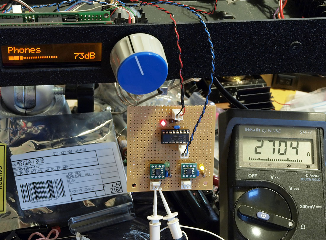
not quite a full build, yet, but its somewhat new.

the old arduino is now controlling 2 digital pot chips!

4291677079_698f6084c7_o.jpg


yeah, I know, ugly rat shack knob. I'll replace it some day (lol).

what's going on in the pic is that the arduino is reading the value from the ugly blue knob and scaling it to an 8bit value (0..255) and showing this in dB. that dB value is then sent out to a port expander chip (phililps dip16 in the perf board) via i2c (blue and black twisted wire). from THAT, we get bunches of 3bit SPI data that is sent to both digital pot chips (the pot chips speak SPI even though the chip above it is i2c). its confusing but I do prefer i2c for doing all my 'control' things and yet the i2c native chips are all tsop and/or use ugly ways to talk to them over i2c. the spi based chips, for some reason, come in soic8 and also dip8 and their software interface is much simpler.

what I plan to use this in: basically anywhere a real pot would go, this thing may be able to fit, also. as an input attenuator before an amp; as a gain setter (feedback R in op-amps), as computer-controlled bass boost (in the amps that have dual pot based BB features) and maybe even auto calibration of bias and offsets in trimmer-settable amps.

the 3 leds are there for debugging; the red one is 'power=ok'; green=global chip-select and orange is global clock.

firmware will be uploaded (source) shortly in case anyone wants to try to replicate/experiment with this.
 
Jan 21, 2010 at 5:15 AM Post #6,261 of 9,811
Quote:

Originally Posted by linuxworks /img/forum/go_quote.gif
not quite a full build, yet, but its somewhat new.

the old arduino is now controlling 2 digital pot chips!

4291677079_698f6084c7_o.jpg


yeah, I know, ugly rat shack knob. I'll replace it some day (lol).

what's going on in the pic is that the arduino is reading the value from the ugly blue knob and scaling it to an 8bit value (0..255) and showing this in dB. that dB value is then sent out to a port expander chip (phililps dip16 in the perf board) via i2c (blue and black twisted wire). from THAT, we get bunches of 3bit SPI data that is sent to both digital pot chips (the pot chips speak SPI even though the chip above it is i2c). its confusing but I do prefer i2c for doing all my 'control' things and yet the i2c native chips are all tsop and/or use ugly ways to talk to them over i2c. the spi based chips, for some reason, come in soic8 and also dip8 and their software interface is much simpler.

what I plan to use this in: basically anywhere a real pot would go, this thing may be able to fit, also. as an input attenuator before an amp; as a gain setter (feedback R in op-amps), as computer-controlled bass boost (in the amps that have dual pot based BB features) and maybe even auto calibration of bias and offsets in trimmer-settable amps.

the 3 leds are there for debugging; the red one is 'power=ok'; green=global chip-select and orange is global clock.

firmware will be uploaded (source) shortly in case anyone wants to try to replicate/experiment with this.


i would love to attempt to integrate the LCDuino-1 with my B1 buffer.
 
Jan 21, 2010 at 1:52 PM Post #6,262 of 9,811
Quote:

Originally Posted by dean0 /img/forum/go_quote.gif
RCA Switchbox I made earlier
-2 Inputs
-4 Outputs


Very nice! Is that a copper plate for ground and rigidity? I am thinking about a similar setup, just housed within the same case as my dac and amp.
 
Jan 21, 2010 at 2:28 PM Post #6,263 of 9,811
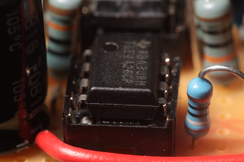
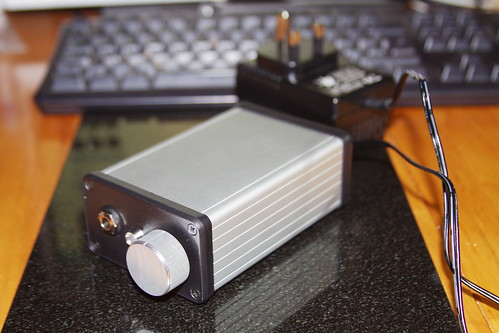
My 3rd build, a cmoy with voltage divider:

TLE2426CP chip (voltage divider)


TAKMAN metal film Resistors:


Finished article:


More to follow, just building a gainclone/starfish combo at the moment.


Linuxworks, Lovely work with the Arduino intergration.. Just got one myself, learning the basics on it at the moment (nice and easy isnt it!) before worrying about intergrating it..

Thanks,
Sam C
 
Jan 21, 2010 at 10:37 PM Post #6,264 of 9,811
Here is my latest creation. It is a relay with a delay for the HV so the filaments can heat up first. I'm putting in my Blue Hawaii.

It has two indicators, one for the power and one for the HV on. I added some additional functionality so that if the umbilical is not connected it will not turn on the HV and just flash the power indicator. This could also be used for thermal sensors too.

Here are the boards. One is the relay and the other is a new version of the BH PS (you gotta tweak
wink.gif
).
bhpsrelayboards004.jpg


Here's the build progress...
bhpsrelayboards009.jpg


bhpsrelayboards010.jpg


bhpsrelayboards012.jpg


bhpsrelayboards016.jpg


I'm not done yet but I've tested the critical parts and it works.
biggrin.gif
Always a concern with new boards.
 
Jan 22, 2010 at 5:00 AM Post #6,266 of 9,811
Kerry,
that's hardcore. please post more pics of your build as you progress.
 
Jan 22, 2010 at 12:34 PM Post #6,267 of 9,811
Kerry as always... damn O.O
Very awesome!
 

Users who are viewing this thread

Back
Top