Post pics of your builds....
Dec 23, 2009 at 4:34 AM Post #6,121 of 9,811
So this is not really electronics, though it will help my hobby
smily_headphones1.gif


The problem was no space to work on projects without my wife looking to kill me. So I'm building this piece of furniture that goes in my dinning room (city living). It will make a nice serving table, but underneath...

It is a place for me to work (daytime - computers / nighttime - electronics).

2009q41222misc011.jpg


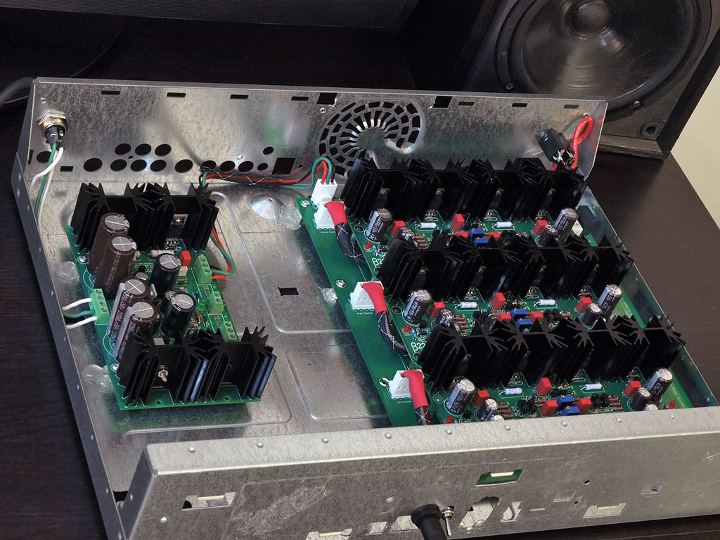
Yes, that is my DIY Blue Hawaii on the left of the shelf
smily_headphones1.gif


Early photo just after I glued the main pieces together (no screws - I used buscuits and glue to join all the wood).

2009q4126misc013.jpg


Here's a shot from the back. The back panels were glued into 1/4" groves that I routed in.
2009q4126misc012.jpg


It's not finished yet, but you can start to get the idea. The front will have doors on either side and the center contains 4 pull out filing draws. There is a 6' work shelf that pulls out 20". It is supported down the center when it is pushed in. Seems rigid enough for now when it is fully extended (as long as there is nothing too heavy in the center).

It's far enought along to be functional. I should finish it up in the next week or two.
 
Dec 23, 2009 at 4:37 AM Post #6,122 of 9,811
Quote:

Originally Posted by linuxworks /img/forum/go_quote.gif
thanks for the nice words, outdoor
wink.gif


fwiw, those 3 boards took me 2 full weekends to build. its a LOT of little things that add up. the time really gets away from you
wink.gif


add in even more time if 'looks matter'. I tried to keep the resistors all pointing the same way with readable value/lables on the top of the part. I tried to make all the top and bottom solder pads look nice and shiny. I did at least 2 full passes of defluxing and board cleaning. I must have desk-checked the board for a total of half an hour, each board, just total 'staring time' to visually inspect things.

I'm not sure how fast one can be built, but on the 'take your time' scale, I'd figure 2 full weekends of JUST soldering and assembly of the raw boards. I have no idea what I'll do (yet) on casing it up but just the soldering, itself, takes a lot longer than I expected.

then again, no one builds a b22 as a 'slam job'. *everyone* takes their time doing a build like this. rushing it could mean an expensive lesson (been there before, myself!)


x2. are you planning on driving efficient speakers as well? i think the B22would sound great with FR speakers.
 
Dec 24, 2009 at 6:40 PM Post #6,123 of 9,811
This has been a very long time coming, and I am absolutely thrilled with the final results...... so apologies for the photo spam, especially if you end up seeing this exact same post on several different forums!

I have just finished up a complete re-case and upgrade of my Buffalo DAC, originally posted here. This is my best attempt at a no holds barred build, while still trying to be a little bit sensible. While it is comprised exclusively of cookie-cutter DIY parts, I would like to think that everything is implemented quite well; I designed it to be clean, functional, and above all, upgradeable.

First some pictures......

buffrd.jpg


bufbkd.jpg


buffr.jpg


bufbk.jpg


Tech highlights:
HiFi2000 Pesante 2U 300mm deep case
FPE panels front (6mm) and back (4mm)
Integrated IEC inlet with DPDT switch, double fused and filter
AMB's E24 with SSR for mains power switching
Two fully shielded and encapsulated 30VA transformers from SumR
Two TPA LCDPS providing four separate power lines for the digital components
One TPA Placid BP with 2.5" sinks providing power for the I/V and linestage, set at ±15V
TPA SPDIF MUX for input switching
USB input provided by AMB's Gamma1 USB/SPDIF board
TPA Toslink input module
Two additional RCA coax inputs
DAC is an original TPA Buffalo24, fed by I2S from the MUX
I/V and linestage is an TPA IVY with the most recent parts recommendations
1pr each XLR and RCA out

Of everything that went into this build, the thing I am most proud of is the Power/Lock light, as shown below. When power is first switched on, the switch lights blue. When SPDIF lock is obtained, the switch changes to red. It is controlled by the LOCK led from the MUX board triggering an OTTO relay wired to reverse the polarity of voltage fed to a Bulgin dual-colour illuminated switch. Such a simple premise, but I absolutely love the functionality it provides, and the cleanliness of the front panel from not needing separate lights. The only problem with this scheme is that when using ASIO through the USB input, the relay clunks around a lot when pausing/resuming and switching tracks. Certainly something I can live with though.

Silence......
bufpow.jpg


Music playing!
buflock.jpg


I still need to add a couple of finishing touches, namely a selector knob, connecting the IEC GND to the chassis, replacing the fasteners with socket head screws, and installing 'struts' that connect the top and bottom plates for better structural rigidity - I'm just going to use a 3" long 6-32 standoff for this, but can't justify the Mouser order for just these, so they will have to wait. I would also like to get a shorter internal USB cable.

Now with respect to being upgradeable, I have tried to keep the power and input system very flexible...... any DAC that takes SPDIF or I2S should drop right in, and the power supplies should be able to handle up to 9V for digital and anywhere in the range of ±12-18V for analogue. And there is an absolutely huge amount of room for new DAC, I/V or linestage boards.

Thanks for looking!
 
Last edited:
Dec 24, 2009 at 7:13 PM Post #6,124 of 9,811
Amazingly clean build, Beefy, that really looks beautiful!
 
Dec 24, 2009 at 7:32 PM Post #6,126 of 9,811
Beefy - that is truly an amazing job. Looks much better than nearly anything on the market, despite being homemade.
 
Dec 24, 2009 at 9:13 PM Post #6,129 of 9,811
Thanks John and everyone else
smily_headphones1.gif


To be honest, its been so long since I listened to my old LCBPS version I couldn't tell you the difference the Placid makes
frown.gif
 
Dec 25, 2009 at 3:32 AM Post #6,131 of 9,811
beefy posted some really PRO level work. it took him a lot of time to design and build that chassis. (and it really looks good, too).

me, otoh, I have not quite gotton into the FPE thang quite yet. but the price was right (free chassis from an old TIVO box, series-1 tivo, to be precise)
wink.gif
I might use it as a base and dress it up (and then mount things for real) or I might abandon it and find something a little nicer for the innerds. but for now, it keeps the power supply from sliding into the amp modules and I suppose that's kind of a good thing.

4212487618_c5c31a6e89_o.jpg


yes, that really is hot-melt glue holding the standoffs to the chassis. it will hold long enough for me to decide on a final layout (that's what I'm fussing about at the moment). I might go with this layout but I also want to reserve room for 'control things'. this has no volume control and it will need one...
wink.gif


but for now, it lets me play with it and that's always a nice middle stage to be at.
 
Dec 25, 2009 at 8:13 PM Post #6,133 of 9,811
I think I picked that up at Newark.

Mouser has plenty of the single colour variants (I bought another plain red one for another build), but doesn't seem to stock the dual colour ones.
 
Dec 26, 2009 at 12:05 AM Post #6,134 of 9,811
Quote:

Originally Posted by Beefy /img/forum/go_quote.gif
Thanks for looking!
smily_headphones1.gif


Thanks for posting. Such a clean build! I am still debating on what to do with my Buffalo. I want something cheap for the time being.
 

Users who are viewing this thread

Back
Top